PCB vs. Cable Backplanes in High-Speed Design: A Comprehensive Comparison
Introduction
In the realm of high-speed digital design, the choice between printed circuit board (PCB) backplanes and cable-based backplane solutions represents one of the most critical decisions system architects must make. This decision impacts not only the immediate performance of the system but also its long-term reliability, scalability, and maintenance requirements. As data rates continue to climb into the multi-gigabit range with emerging standards like PCIe 5.0 (32 GT/s), 112G PAM4, and beyond, the backplane selection becomes increasingly crucial for signal integrity and overall system performance.
This article provides a detailed comparison of PCB and cable backplane technologies, examining their respective advantages, limitations, and optimal use cases in high-speed design environments. We’ll explore technical considerations including signal integrity, power delivery, thermal management, density, cost factors, and future scalability.
Fundamentals of Backplane Technologies
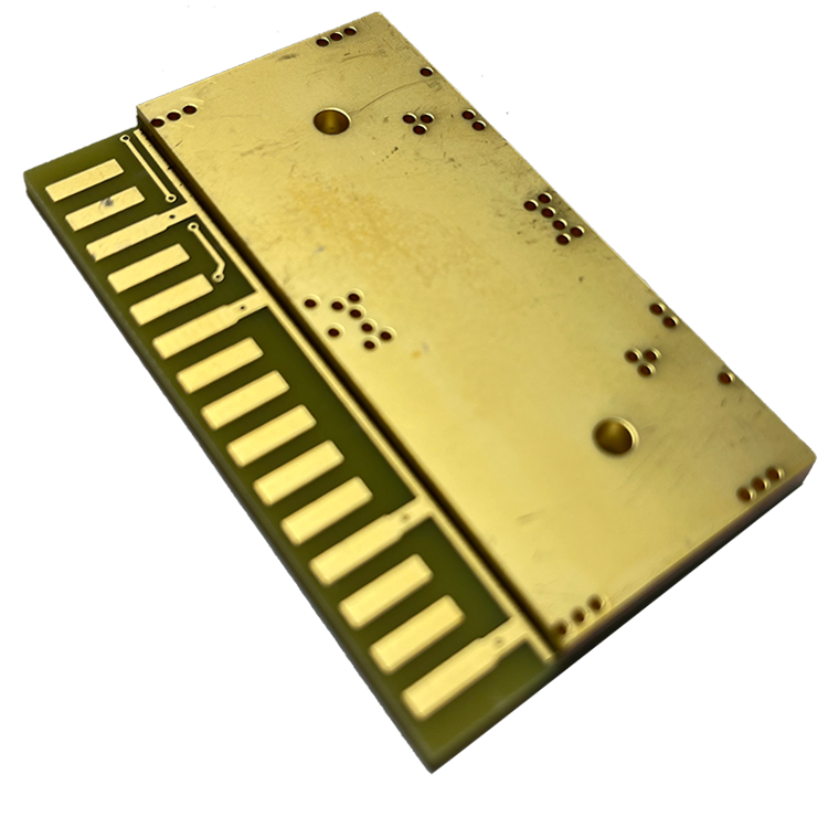
PCB Backplanes
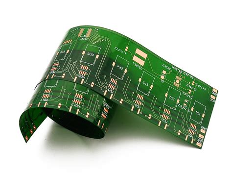
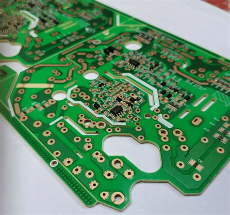
PCB backplanes represent the traditional approach to system interconnection. These are essentially large, multilayer printed circuit boards that provide both electrical connectivity and mechanical support for daughter cards or line cards. The backplane contains plated through holes or high-density connectors that allow perpendicular or parallel connection of multiple boards in a rack or chassis.
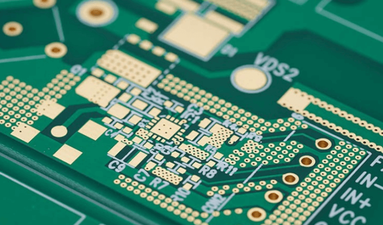
Modern high-speed PCB backplanes typically utilize:
- High-performance laminate materials (Megtron 6, Rogers, Isola FR408HR)
- Advanced via structures (blind, buried, and microvias)
- Controlled impedance routing with length matching
- Sophisticated equalization techniques
- 20+ layers in complex designs
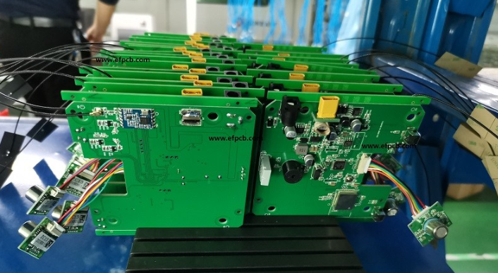
Cable Backplanes
Cable backplane solutions replace traditional PCB traces with controlled-impedance cable assemblies. These systems use either discrete coaxial cables or ribbon-style cable assemblies (like Samtec’s Flyover® technology) to route signals between connectors. The cables typically terminate in high-density connectors that interface with daughter cards.
Modern cable backplane implementations feature:
- Twinaxial or differential pair cable constructions
- Integrated shielding for EMI control
- Precision skew management
- Active cable technologies
- Flexible routing topologies
Performance Comparison
Signal Integrity Considerations
PCB Backplanes:
- Face challenges with dielectric losses (Df) at high frequencies
- Require sophisticated equalization (CTLE, DFE, FFE) above 10 Gbps
- Limited by via stub effects and connector transitions
- Impedance control becomes more difficult with increasing layer counts
- Typical reach: ~20 inches for 56G PAM4 with advanced materials
Cable Backplanes:
- Superior high-frequency performance due to consistent dielectric properties
- Lower insertion loss (typically 0.5-1.5 dB/inch at 25 GHz vs. 2-4 dB/inch for PCB)
- Minimized discontinuities at connection points
- Less dependent on advanced equalization up to ~32 Gbps
- Can achieve 50+ inches reach at 56G PAM4 rates
Bandwidth and Data Rate Support
PCB technology has made significant strides with the development of low-loss materials and improved manufacturing techniques. While early PCB backplanes struggled beyond 10 Gbps, modern implementations using materials like Megtron 6 or Rogers can support:
- 16-32 Gbps NRZ (PCIe 4.0/5.0, SAS-4)
- 56-112 Gbps PAM4 (400G/800G Ethernet)
However, cable backplanes consistently outperform PCBs at these higher data rates, with demonstrated capabilities:
- 64 Gbps NRZ in prototype systems
- 112 Gbps PAM4 in production environments
- Clear path to 224 Gbps PAM4 for future standards
Latency Comparison
For latency-sensitive applications (high-frequency trading, real-time processing):
- PCB backplanes offer slightly lower latency for short reaches (<12 inches)
- Cable solutions introduce about 1.4-1.6 ns/ft additional propagation delay
- The difference becomes negligible for longer reaches where PCB requires retimers
Physical Design Considerations
Density and Form Factor
PCB Backplanes:
- Enable very high connector density (1000+ contacts per linear inch)
- Support orthogonal, mid-plane, or parallel board configurations
- Fixed routing requires careful planning
- Thickness grows with layer count (up to 0.5″ for complex designs)
Cable Backplanes:
- Generally lower density than PCB solutions
- More flexible in physical arrangement (cables can route around obstacles)
- Enable non-orthogonal board arrangements
- Thinner profile possible but cables occupy more volume
Thermal Management
PCB backplanes:
- Act as heat spreaders for some thermal loads
- Can incorporate thermal vias and planes
- Limited thermal expansion mismatch with daughter cards
Cable backplanes:
- Cables generate minimal heat compared to PCB dielectric losses
- Allow more airflow through the chassis
- May require separate cooling strategies for connectors
Mechanical Considerations
PCB backplanes:
- Provide rigid structural support
- Fixed configuration requires precise alignment
- Vulnerable to flexure and vibration-induced failures
Cable backplanes:
- More tolerant of mechanical stress and vibration
- Enable modular replacement of individual links
- May require additional support structures
Cost Analysis
Initial Costs
PCB backplanes:
- High NRE costs for design and tooling
- Economies of scale at high volumes
- Material costs significant for advanced laminates
Cable backplanes:
- Lower initial tooling costs
- Higher per-unit costs at moderate volumes
- Cost-effective for low/medium volume production
Lifecycle Costs
PCB backplanes:
- Difficult to modify after manufacture
- Entire assembly often replaced for upgrades
- Longer lead times for complex designs
Cable backplanes:
- Field-reconfigurable to some extent
- Individual cables can be replaced
- Faster prototyping iterations possible
Reliability and Maintenance
PCB backplanes:
- Single point of failure for the entire system
- Vulnerable to mechanical damage
- Complex repair processes
Cable backplanes:
- Graceful degradation possible
- Easier field serviceability
- Modular replacement reduces downtime
Application-Specific Considerations
Best Use Cases for PCB Backplanes
- High-density systems requiring thousands of connections
- Applications with space constraints that can’t accommodate cable bulk
- Cost-sensitive, high-volume production
- Systems requiring rigid mechanical structure
- Environments with extreme temperature cycling
Best Use Cases for Cable Backplanes
- Ultra-high-speed links (>32 Gbps NRZ, >56 Gbps PAM4)
- Prototyping and development environments
- Systems requiring field configurability
- Applications with severe vibration or mechanical stress
- Long-reach connections within chassis
Future Trends and Emerging Technologies
PCB Technology Advancements
- Ultra-low loss materials (Df < 0.001)
- Photonic integrated circuits for optical backplanes
- Embedded active components (retimers in PCB)
- 3D printed electronics for customized backplanes
Cable Technology Innovations
- Active optical cables for >112G applications
- Higher density cable connectors
- Integrated power delivery in cable assemblies
- Intelligent cables with embedded diagnostics
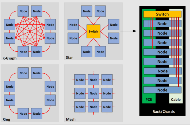
Hybrid Approaches
Many modern systems employ hybrid solutions that combine the strengths of both technologies:
- PCB for power distribution and low-speed signals
- Cables for high-speed serial links
- PCB with cable “flyovers” for critical paths
This approach is particularly common in:
- High-performance computing clusters
- 5G infrastructure equipment
- Advanced military/aerospace systems
Conclusion
The choice between PCB and cable backplanes in high-speed design involves careful consideration of multiple technical and business factors. PCB backplanes remain the dominant solution for high-density, cost-sensitive applications where data rates are below 32 Gbps NRZ. Their ability to provide both electrical connectivity and mechanical structure makes them indispensable in many traditional architectures.
However, as data rates push into the 56G PAM4 and 112G PAM4 regimes, cable backplane solutions offer compelling advantages in signal integrity, manufacturability, and field serviceability. They are particularly valuable in prototyping environments, low-to-medium volume production, and systems requiring exceptional high-frequency performance.
System designers must evaluate their specific requirements for bandwidth, density, cost, and reliability when making this critical architectural decision. Increasingly, the optimal solution may involve a strategic combination of both technologies, leveraging PCB for power distribution and control signals while employing cable interconnects for the most demanding high-speed serial links.
As data rates continue their relentless climb, both technologies will evolve, but the fundamental tradeoffs between integrated PCB solutions and modular cable approaches will remain a central consideration in high-speed system architecture.