pcb z-axis milling
OptimizingDepth for Precision PCB Z-Axis Milling
Optimizing the Z-axis depth for precision PCB milling is a critical aspect of ensuring high-quality printed circuit boards. The Z-axis, which controls the vertical movement of the milling tool, plays a pivotal role in determining the accuracy and efficiency of the milling process. Proper calibration and control of this axis can significantly impact the final product, making it essential for engineers and technicians to understand the nuances involved.
To begin with, the Z-axis depth must be meticulously calibrated to achieve the desired milling depth.
This calibration involves setting the zero point, which is the reference point from which all vertical measurements are taken. An accurate zero point ensures that the milling tool engages the PCB material at the correct depth, preventing issues such as over-milling or under-milling. Over-milling can lead to excessive material removal, potentially damaging the PCB and compromising its structural integrity. Conversely, under-milling can result in incomplete traces and connections, leading to functional failures.
Furthermore, the choice of milling tool and its corresponding settings are crucial in optimizing Z-axis depth.
Different tools have varying cutting capabilities and are designed for specific materials and thicknesses. Selecting the appropriate tool for the job ensures that the milling process is both efficient and precise. Additionally, adjusting the spindle speed and feed rate in accordance with the tool specifications can enhance the milling quality. A higher spindle speed may be necessary for harder materials, while a slower feed rate can improve the accuracy of intricate designs.
Another important consideration is the material of the PCB itself.
Different materials, such as FR4, aluminum, or flexible substrates, have unique properties that affect how they respond to milling. Understanding these properties allows for better control of the Z-axis depth, ensuring that the milling tool interacts with the material in an optimal manner. For instance, FR4, a common PCB material, requires careful handling to avoid delamination or excessive wear on the milling tool.
In addition to material considerations, the design of the PCB also influences the Z-axis depth optimization.
Complex designs with multiple layers or fine traces necessitate precise control over the milling depth to avoid damaging underlying layers or adjacent traces. Utilizing advanced software tools for design and simulation can aid in predicting potential issues and adjusting the milling parameters accordingly. These tools can simulate the milling process, providing valuable insights into how the Z-axis depth will affect the final product.
Moreover, regular maintenance and calibration of the milling machine are essential for maintaining optimal Z-axis performance.
Over time, mechanical components can wear out or become misaligned, leading to inaccuracies in the milling process. Routine checks and adjustments ensure that the machine operates within its specified tolerances, thereby maintaining the precision required for high-quality PCB production.
In conclusion, optimizing the Z-axis depth for precision PCB milling involves a combination of accurate calibration, appropriate tool selection, material understanding, and regular machine maintenance. By paying close attention to these factors, engineers and technicians can achieve superior milling results, leading to reliable and high-performance printed circuit boards. The interplay between these elements underscores the importance of a holistic approach to PCB milling, where each aspect is carefully considered to ensure the best possible outcome.
Common Challenges in Z-Axis PCB Milling and How to Overcome Them
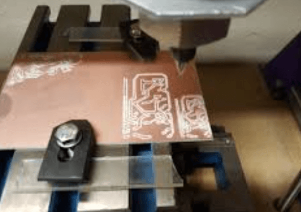
Z-axis PCB milling, a critical process in the fabrication of printed circuit boards, involves the precise removal of material to create intricate patterns and pathways. Despite its importance, this process is fraught with challenges that can significantly impact the quality and functionality of the final product. Understanding these common challenges and how to overcome them is essential for achieving optimal results.
One of the primary challenges in Z-axis PCB milling is maintaining the correct depth of cut.
The depth of cut is crucial because it determines the thickness of the remaining material, which in turn affects the electrical properties of the PCB. Inconsistent depth can lead to variations in impedance, potentially causing signal integrity issues. To address this, it is essential to use a milling machine with high precision and stability. Additionally, implementing a robust calibration routine before each milling session can help ensure that the cutting tool maintains the correct depth throughout the process.
Another significant challenge is tool wear and breakage.
The cutting tools used in Z-axis PCB milling are typically made of carbide or diamond, materials known for their hardness and durability. However, even these materials can wear down or break under the high-stress conditions of milling. Tool wear can lead to poor cutting performance, resulting in rough edges and incomplete cuts. To mitigate this issue, it is advisable to regularly inspect and replace cutting tools. Employing a tool monitoring system can also help detect signs of wear early, allowing for timely intervention.
Surface finish quality is another area of concern in Z-axis PCB milling.
A poor surface finish can lead to issues such as poor solderability and increased risk of short circuits. Achieving a smooth surface finish requires careful control of milling parameters, including spindle speed, feed rate, and cutting depth. Using high-quality cutting tools and ensuring they are sharp can also contribute to a better surface finish. Additionally, employing a coolant or lubricant during the milling process can help reduce friction and heat, further improving the surface quality.
Material selection poses another challenge in Z-axis PCB milling.
Different PCB materials, such as FR4, Rogers, and polyimide, have varying properties that can affect the milling process. For instance, FR4 is a common material that is relatively easy to mill, but it can produce fine dust that may pose health risks if not properly managed. On the other hand, Rogers materials are known for their excellent electrical properties but can be more challenging to mill due to their hardness. Understanding the properties of the material being milled and selecting appropriate milling parameters can help overcome these challenges.
Lastly, managing the removal of debris and dust generated during the milling process is crucial.
Accumulated debris can interfere with the milling operation, leading to inaccuracies and potential damage to the PCB. Implementing an effective dust extraction system can help keep the milling area clean and free of obstructions. Regular maintenance of the milling machine, including cleaning and lubrication, can also contribute to smoother operation and better results.
In conclusion, Z-axis PCB milling presents several challenges that can impact the quality and functionality of the final product. By maintaining the correct depth of cut, managing tool wear, ensuring a high-quality surface finish, selecting appropriate materials, and effectively removing debris, these challenges can be effectively addressed. Through careful planning and attention to detail, it is possible to achieve optimal results in Z-axis PCB milling, ensuring the production of high-quality printed circuit boards.
Essential Tools for Accurate Z-Axis PCB Milling
Accurate Z-axis PCB milling is a critical aspect of printed circuit board (PCB) fabrication, requiring precision and the right set of tools to achieve optimal results. The Z-axis, which controls the depth of the milling process, plays a pivotal role in ensuring that the PCB traces are correctly etched and that the board’s integrity is maintained. To achieve this level of precision, several essential tools are indispensable.
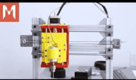
First and foremost, a high-quality CNC milling machine is the cornerstone of accurate Z-axis PCB milling.
These machines are designed to offer precise control over the milling process, allowing for intricate designs and fine details to be accurately reproduced on the PCB. The CNC machine should have a robust and stable frame to minimize vibrations, which can adversely affect the milling accuracy. Additionally, the machine should be equipped with a reliable spindle that can maintain consistent speeds, as fluctuations can lead to uneven milling depths.
Equally important is the use of appropriate milling bits.
These bits come in various shapes and sizes, each suited for different milling tasks. For Z-axis milling, end mills with a flat bottom are commonly used as they provide a clean and even cut. The diameter of the milling bit should be chosen based on the width of the traces and the overall design of the PCB. Smaller bits are ideal for intricate designs, while larger bits can be used for more substantial cuts. It is also crucial to ensure that the milling bits are sharp and in good condition, as dull bits can cause inaccuracies and damage the PCB material.
Another essential tool for accurate Z-axis PCB milling is a precise height probe or touch plate.
This device is used to determine the exact height of the PCB surface, allowing the CNC machine to adjust the Z-axis accordingly. By accurately measuring the height, the milling machine can ensure that the milling depth is consistent across the entire board, which is vital for maintaining the integrity of the PCB traces. The height probe should be calibrated regularly to ensure its accuracy.
In addition to the hardware, the software used to control the CNC machine is equally important.
Advanced CNC software allows for precise control over the milling process, including the Z-axis movements. The software should be capable of generating accurate toolpaths based on the PCB design files, ensuring that the milling machine follows the correct paths and depths. Furthermore, the software should offer features such as automatic toolpath optimization and error detection, which can help prevent mistakes and improve the overall milling accuracy.
Moreover, a stable and flat work surface is essential for accurate Z-axis PCB milling.
The PCB material should be securely clamped to the work surface to prevent any movement during the milling process. Any movement or shifting of the PCB can result in uneven milling depths and inaccuracies in the final product. Using a vacuum table or double-sided tape can help secure the PCB material firmly in place.
Finally, regular maintenance and calibration of the CNC machine and its components are crucial for maintaining accuracy in Z-axis PCB milling.
This includes checking the alignment of the machine, ensuring that the spindle is running smoothly, and replacing worn-out milling bits. By keeping the equipment in optimal condition, one can achieve consistent and accurate results in PCB milling.
In conclusion, accurate Z-axis PCB milling requires a combination of high-quality tools, precise measurement devices, advanced software, and regular maintenance. By investing in the right equipment and ensuring that it is properly maintained, one can achieve the precision needed for high-quality PCB fabrication.
Step-by-Step Guide to Setting Up Z-Axis Parameters for PCB Milling
Setting up the Z-axis parameters for PCB milling is a critical step that ensures precision and accuracy in the milling process. The Z-axis, which controls the vertical movement of the milling tool, plays a pivotal role in determining the depth of cuts and the overall quality of the milled PCB. To begin with, it is essential to understand the importance of calibrating the Z-axis accurately. This calibration ensures that the milling tool engages with the PCB material at the correct depth, thereby preventing damage to the tool and the material.
The first step in setting up the Z-axis parameters involves securing the PCB material firmly on the milling machine’s work surface.
This can be achieved using clamps or a vacuum table, depending on the machine’s design. Ensuring that the PCB is flat and stable is crucial, as any movement during milling can lead to inaccuracies. Once the PCB is secured, the next step is to install the milling tool. It is important to choose the appropriate tool for the specific milling task, as different tools are designed for different types of cuts and materials.
After installing the milling tool, the next step is to set the zero point for the Z-axis.
This zero point serves as a reference for all subsequent milling operations. To set the zero point, manually lower the milling tool until it just touches the surface of the PCB material. This can be done using the machine’s control software or manually, depending on the machine’s capabilities. Once the tool is in contact with the PCB surface, set the Z-axis coordinate to zero in the control software. This establishes the starting point for all Z-axis movements.
Following the establishment of the zero point, it is necessary to configure the cutting depth parameters.
The cutting depth determines how deep the milling tool will cut into the PCB material. This parameter is critical, as cutting too deep can damage the PCB, while cutting too shallow may not achieve the desired results. The cutting depth is typically specified in the design files and should be entered accurately into the control software. It is advisable to perform a test cut on a scrap piece of PCB material to verify that the cutting depth is set correctly.
In addition to setting the cutting depth, it is also important to configure the feed rate and spindle speed.
The feed rate refers to the speed at which the milling tool moves across the PCB surface, while the spindle speed refers to the rotational speed of the milling tool. Both parameters should be set according to the manufacturer’s recommendations and the specific requirements of the milling task. Incorrect settings can lead to poor milling quality and potential damage to the tool and material.
Once all parameters are configured, it is essential to perform a final check before starting the milling process.
Verify that the PCB material is securely fastened, the milling tool is properly installed, and all Z-axis parameters are correctly set. Additionally, ensure that the work area is clear of any obstructions and that all safety precautions are in place.
In conclusion, setting up the Z-axis parameters for PCB milling requires careful attention to detail and a thorough understanding of the milling process. By following these steps and ensuring that all parameters are accurately configured, one can achieve precise and high-quality milling results. Proper setup not only enhances the efficiency of the milling process but also extends the lifespan of the milling tools and equipment.


