Power Integrity in PCB Design: Fundamentals, Challenges, and Solutions
1. Introduction
Power Integrity (PI) is a critical aspect of printed circuit board (PCB) design that ensures stable and reliable power delivery to all components. As modern electronic devices demand higher performance, lower power consumption, and faster switching speeds, maintaining power integrity becomes increasingly challenging. Poor power integrity can lead to signal integrity issues, electromagnetic interference (EMI), and even system failures.
This article explores the fundamentals of power integrity, key challenges in PCB design, and effective solutions to mitigate power-related issues.
2. Fundamentals of Power Integrity
Power integrity refers to the ability of a power distribution network (PDN) to deliver clean and stable voltage to all components on a PCB. The primary goals of PI are:
- Minimizing voltage fluctuations (ripple and noise).
- Reducing impedance in the PDN to prevent voltage drops.
- Ensuring sufficient current delivery to high-speed components.
2.1 Key Concepts in Power Integrity
- Power Distribution Network (PDN):
The PDN consists of voltage regulators, decoupling capacitors, power planes, and vias that deliver power from the source to ICs. An optimized PDN minimizes resistance, inductance, and capacitance (RLC) effects. - Target Impedance:
The PDN must maintain a low impedance across a wide frequency range to prevent voltage fluctuations. The target impedance is calculated as:
[
Z_{target} = \frac{\Delta V}{I_{max}}
]
Where ( \Delta V ) is the allowable voltage ripple, and ( I_{max} is the maximum current demand. - Decoupling Capacitors:
These capacitors suppress high-frequency noise by providing localized charge storage near ICs. Proper selection and placement are crucial for effective decoupling. - Power Plane Design:
Solid power and ground planes reduce inductance and provide a low-impedance return path for high-speed signals.
3. Challenges in Power Integrity
Several factors complicate power integrity in modern PCBs:
3.1 High-Speed Switching and Transient Currents
Modern processors and FPGAs draw large, fast-changing currents, causing simultaneous switching noise (SSN). If the PDN cannot respond quickly, voltage droops (sags) or spikes occur, leading to timing errors or logic failures.
3.2 Parasitic Inductance and Resistance
- Inductive voltage drops (( V = L \frac{di}{dt} )) worsen with faster edge rates.
- Resistive losses (IR drop) increase with higher currents, leading to excessive heating.
3.3 Resonances and Antenna Effects
Poorly designed PDNs can act as antennas, radiating EMI. Power-ground plane cavities also form parasitic resonances, amplifying noise at certain frequencies.
3.4 Multi-Layer PCB Complexity
High-density interconnects (HDI) and mixed-signal designs introduce coupling between power and signal layers, complicating noise isolation.
4. Power Integrity Analysis Techniques
To ensure robust PI, engineers use several analysis methods:
4.1 Frequency Domain Analysis
- Impedance Profile Analysis: Evaluates PDN impedance vs. frequency using tools like Ansys SIwave or Cadence Sigrity.
- S-Parameter Models: Characterize PDN behavior in high-frequency applications.
4.2 Time Domain Analysis
- Transient Simulations: Assess voltage ripple and droop under dynamic loads.
- Power Delivery Network Simulation: Tools like HyperLynx PI analyze DC and AC performance.
4.3 Measurement Techniques
- Vector Network Analyzer (VNA): Measures PDN impedance.
- Oscilloscope Probing: Captures real-time voltage fluctuations.
5. Best Practices for Power Integrity Optimization
To mitigate PI issues, PCB designers should follow these best practices:
5.1 Optimize Decoupling Capacitor Strategy
- Use a mix of bulk, ceramic, and high-frequency capacitors.
- Place decoupling capacitors as close as possible to IC power pins.
- Follow the “rule of thumb” for capacitor values (e.g., 0.1µF for mid-frequency, 1-10µF for bulk decoupling).
5.2 Low-Impedance Power Plane Design
- Use wide power traces and solid planes to minimize resistance.
- Implement split power planes for mixed-voltage designs while ensuring proper isolation.
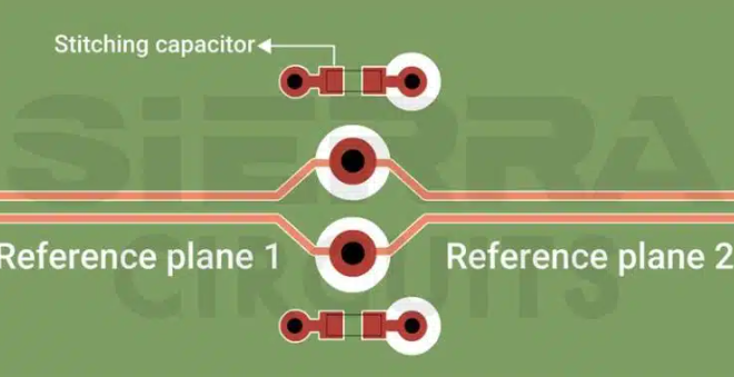
5.3 Proper Grounding Techniques
- Use a low-inductance ground return path.
- Avoid ground loops by implementing a star grounding scheme in mixed-signal designs.
5.4 Power Integrity-Aware PCB Stackup
- Place power and ground planes adjacent to each other to maximize capacitance.
- Use thin dielectrics between planes to reduce loop inductance.
5.5 Advanced Techniques
- Active Voltage Regulation (AVR): Dynamically adjusts voltage to compensate for droop.
- Embedded Passive Components: Reduces parasitic effects by integrating decoupling capacitors inside the PCB.
6. Case Study: Power Integrity in High-Speed Digital Design
Consider a high-performance FPGA board with a 1.0V core supply and 100A transient current demand. The allowable ripple is ±3% (30mV). The target impedance is:
[
Z_{target} = \frac{30mV}{100A} = 0.3mΩ
]
To achieve this:
- Decoupling Network: A combination of 10µF, 1µF, and 0.1µF capacitors is used.
- Power Plane Optimization: Thin (2-4 mil) dielectric layers between power and ground planes reduce inductance.
- Simulation: Pre-layout and post-layout PDN analysis ensures impedance stays below 0.3mΩ up to 100MHz.
7. Future Trends in Power Integrity
As technology advances, new challenges emerge:
- Higher Current Demands: AI/ML processors require advanced cooling and power delivery.
- 3D-IC and Chiplets: Heterogeneous integration complicates PDN design.
- Wide-Bandgap Semiconductors (GaN/SiC): Faster switching increases EMI risks.
Emerging solutions include:
- AI-Driven PI Optimization: Machine learning predicts noise hotspots.
- Advanced Materials: Low-loss dielectrics and embedded power regulators.
8. Conclusion
Power integrity is a critical factor in PCB design, affecting performance, reliability, and EMI compliance. By understanding PDN fundamentals, analyzing impedance, and implementing best practices, engineers can mitigate power-related issues. As electronics evolve, continuous innovation in PI techniques will be essential for next-generation designs.
References
- Bogatin, E. (2018). Signal and Power Integrity – Simplified.
- Ritchey, L. W. (2019). Right the First Time: A Practical Handbook on High-Speed PCB and System Design.
- IEEE Standards on Power Integrity Analysis.