Practical Tips and Methods for Troubleshooting PCB Circuit Board Failures
Introduction
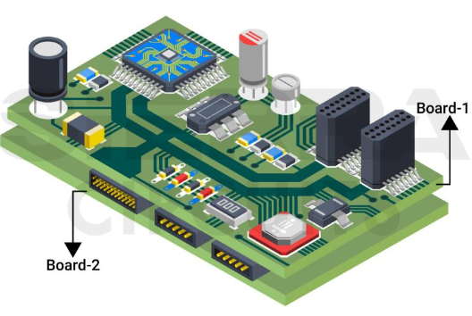
Printed Circuit Boards (PCBs) are the backbone of modern electronics, found in everything from smartphones to industrial machinery. However, like any electronic component, PCBs can develop faults due to manufacturing defects, environmental factors, or wear and tear. Effective troubleshooting is essential to identify and resolve these issues efficiently. This article explores practical techniques and methods for diagnosing and repairing common PCB failures.
1. Visual Inspection
Before diving into complex diagnostics, a thorough visual inspection can often reveal obvious issues.
Key Steps:
- Check for Physical Damage: Look for cracks, burns, or warping on the PCB.
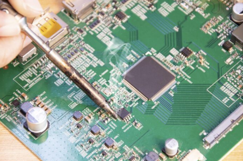
- Examine Soldering Joints: Cold solder joints, bridging, or insufficient solder can cause connectivity issues.
- Inspect Components: Look for burnt, swollen, or leaking capacitors, damaged resistors, or loose ICs.
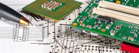
- Trace Integrity: Verify that copper traces are intact and not corroded or broken.
Tools Needed:
- Magnifying glass or microscope
- Bright lighting
- Multimeter (for continuity checks)

2. Power Supply Testing
Many PCB failures stem from power-related issues.
Common Power Problems:
- No Power: Check input voltage, fuses, and regulators.
- Fluctuating Voltage: Test for unstable output from voltage regulators.
- Short Circuits: Use a multimeter in continuity mode to detect unintended connections.
Testing Procedure:
- Measure input voltage at the power connector.
- Verify voltage levels at key ICs and regulators.
- Check for excessive current draw indicating a short.
Tools Needed:
- Digital multimeter (DMM)
- Oscilloscope (for ripple analysis)
3. Signal Tracing & Functional Testing
If power is stable but the PCB isn’t functioning correctly, signal tracing helps isolate the fault.
Techniques:
- Follow the Signal Path: Use an oscilloscope to check waveforms at different stages.
- Compare with a Working PCB: If available, compare signals between a faulty and functional board.
- Check Clock Signals: Ensure microcontrollers and processors receive proper clock signals.
Common Issues:
- Missing or distorted signals
- Incorrect logic levels
- Signal reflections due to impedance mismatches
Tools Needed:
- Oscilloscope
- Logic analyzer
- Function generator (for signal injection)
4. Component-Level Testing
Individual components (resistors, capacitors, transistors, ICs) can fail and need verification.
Testing Methods:
- Resistors & Capacitors: Use a multimeter to measure resistance/capacitance.
- Diodes & Transistors: Perform diode-mode tests with a DMM.
- ICs: Verify power pins, check for overheating, or use an IC tester.
Common Faults:
- Open or shorted components
- Drifted values (e.g., capacitors losing capacitance)
- Overheated or burnt ICs
Tools Needed:
- LCR meter (for precise component measurements)
- Thermal camera (for detecting overheating parts)
5. Thermal Analysis
Overheating is a leading cause of PCB failure.
Diagnostic Steps:
- Run the PCB Under Load: Monitor temperature with a thermal camera or IR thermometer.
- Identify Hotspots: Overheating components may indicate excessive current or poor heat dissipation.
- Check Cooling Systems: Ensure fans or heat sinks are functioning.
Common Causes of Overheating:
- Poor thermal design
- Short circuits
- Overloaded components
Tools Needed:
- Infrared thermometer
- Thermal imaging camera
6. Firmware & Software Debugging
Some PCB issues stem from firmware or software errors rather than hardware faults.
Debugging Techniques:
- Check for Firmware Corruption: Reflash the firmware if possible.
- Monitor Debug Logs: Use UART, JTAG, or SWD interfaces for debugging.
- Test with Known Good Code: Compare behavior with a working version.
Common Issues:
- Boot failures
- Frozen or unresponsive systems
- Incorrect sensor readings due to software bugs
Tools Needed:
- Debugger (ST-Link, J-Link, etc.)
- Serial terminal (PuTTY, Tera Term)
7. Environmental & Interference Issues
External factors like EMI, humidity, or vibration can cause intermittent failures.
Troubleshooting Steps:
- Check for EMI/RFI Interference: Use shielded cables or ferrite beads.
- Inspect for Moisture Damage: Look for corrosion or oxidation.
- Test Under Different Conditions: Vary temperature and humidity to replicate failures.
Common Fixes:
- Improve grounding and shielding
- Apply conformal coating for moisture protection
- Secure loose connectors
8. Advanced Techniques (When Basic Methods Fail)
For complex issues, advanced tools may be necessary.
Methods:
- X-Ray Inspection: Detects hidden solder defects (e.g., BGA voids).
- Time-Domain Reflectometry (TDR): Locates trace discontinuities.
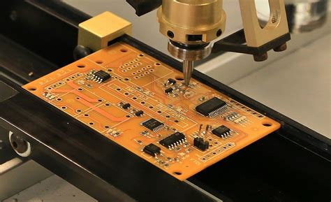
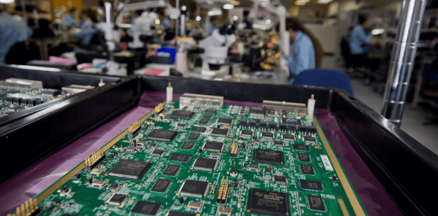
- Automated Optical Inspection (AOI): Used in manufacturing for defect detection.
When to Use Advanced Tools:
- Intermittent faults with no obvious cause
- High-density PCBs with hidden layers
- Suspected micro-cracks or internal delamination
Conclusion
Troubleshooting PCB failures requires a systematic approach, starting with visual inspection and progressing to advanced diagnostics when needed. By combining power testing, signal analysis, component checks, and environmental assessments, engineers and technicians can efficiently identify and resolve PCB faults. Continuous learning and access to the right tools are key to mastering PCB repair.
By following these practical tips, you can minimize downtime, reduce repair costs, and extend the lifespan of electronic devices.