Printed Circuit Board (PCB) Reliability: Challenges, Testing, and Improvement Strategies
Abstract
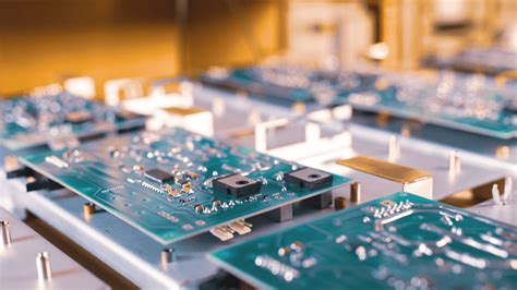
Printed Circuit Boards (PCBs) are the backbone of modern electronics, serving as the foundation for interconnecting electronic components in devices ranging from smartphones to industrial machinery. As the demand for smaller, faster, and more complex electronic systems grows, ensuring the reliability of PCBs has become a critical concern. This article explores the factors affecting PCB reliability, common failure mechanisms, testing methodologies, and strategies to enhance reliability throughout the design, manufacturing, and operational phases.
1. Introduction
The reliability of a PCB is defined as its ability to perform its intended function under specified conditions for a designated period of time. Given the increasing complexity of electronic systems and the harsh environments in which they often operate, ensuring PCB reliability is a multifaceted challenge. Failures in PCBs can lead to catastrophic consequences, especially in critical applications such as aerospace, automotive, and medical devices. Therefore, understanding the factors that influence PCB reliability and implementing robust design and manufacturing practices are essential.
This article provides a comprehensive overview of PCB reliability, covering key challenges, failure mechanisms, testing techniques, and strategies for improvement.
2. Factors Affecting PCB Reliability
Several factors influence the reliability of PCBs, including material selection, design, manufacturing processes, and operational conditions. Below are the primary factors:
2.1 Material Selection
The materials used in PCB fabrication, such as the substrate, copper, solder mask, and surface finish, play a significant role in determining reliability. For example:
- Substrate Material: The most common substrate material is FR-4, a glass-reinforced epoxy laminate. However, high-frequency or high-temperature applications may require advanced materials like polyimide or ceramic-filled PTFE.
- Copper Quality: The purity and thickness of copper traces affect electrical performance and thermal management.
- Solder Mask: A high-quality solder mask protects against environmental factors like moisture and contaminants.
- Surface Finish: Surface finishes such as HASL (Hot Air Solder Leveling), ENIG (Electroless Nickel Immersion Gold), and OSP (Organic Solderability Preservative) impact solderability and corrosion resistance.
2.2 Design Considerations
PCB design is a critical factor in reliability. Poor design can lead to issues such as signal integrity problems, thermal stress, and mechanical failures. Key design considerations include:
- Trace Width and Spacing: Proper trace width and spacing are essential to prevent short circuits and ensure signal integrity.
- Thermal Management: Inadequate heat dissipation can lead to component failure. Thermal vias, heat sinks, and proper component placement are crucial.
- Mechanical Stress: Designs should account for mechanical stress caused by vibration, shock, or flexing, especially in flexible or rigid-flex PCBs.
2.3 Manufacturing Processes
The manufacturing process can introduce defects that compromise reliability. Common issues include:
- Misalignment: Misalignment during layer stacking can cause short circuits or open circuits.
- Solder Joint Defects: Poor soldering can result in cold joints, voids, or insufficient wetting.
- Contamination: Residual flux or other contaminants can lead to corrosion or electrical leakage.
2.4 Operational Conditions
PCBs are often subjected to harsh operational conditions, including:
- Temperature Extremes: Thermal cycling can cause expansion and contraction, leading to mechanical stress.
- Humidity and Moisture: Moisture ingress can cause corrosion or delamination.
- Vibration and Shock: Mechanical stress can weaken solder joints or damage components.
3. Common PCB Failure Mechanisms
Understanding the failure mechanisms of PCBs is essential for improving reliability. The most common failure mechanisms include:
3.1 Thermal Stress
Thermal stress occurs due to differences in the coefficient of thermal expansion (CTE) between materials. Repeated thermal cycling can lead to:
- Solder Joint Fatigue: Cracking or failure of solder joints.
- Delamination: Separation of PCB layers due to thermal expansion.
3.2 Electromigration
Electromigration is the movement of metal atoms caused by high current density, leading to the formation of voids or hillocks. This can result in open circuits or short circuits.
3.3 Corrosion
Corrosion occurs when metals react with environmental factors such as moisture or contaminants. Common types include:
- Galvanic Corrosion: Occurs when dissimilar metals are in contact in the presence of an electrolyte.
- Electrochemical Migration: Formation of conductive metal filaments due to ion migration.
3.4 Mechanical Failure
Mechanical failure can result from vibration, shock, or improper handling. Examples include:
- Cracked Traces: Fractures in copper traces due to mechanical stress.
- Component Damage: Physical damage to components during assembly or operation.
3.5 Electrical Overstress
Electrical overstress (EOS) occurs when a PCB is subjected to voltage or current beyond its design limits, leading to:
- Dielectric Breakdown: Failure of insulating materials.
- Component Burnout: Damage to components due to excessive heat.
4. PCB Reliability Testing
Reliability testing is essential to identify potential failures and validate the performance of PCBs under various conditions. Common testing methodologies include:
4.1 Environmental Testing
Environmental testing evaluates the performance of PCBs under extreme conditions:
- Thermal Cycling: Exposes the PCB to alternating high and low temperatures to assess thermal stress resistance.
- Humidity Testing: Evaluates the PCB’s resistance to moisture and corrosion.
- Vibration and Shock Testing: Assesses the PCB’s ability to withstand mechanical stress.
4.2 Electrical Testing
Electrical testing ensures the PCB meets its electrical performance requirements:
- Continuity Testing: Verifies the integrity of electrical connections.
- Insulation Resistance Testing: Measures the resistance between conductive traces to detect insulation defects.
- High-Potential (Hi-Pot) Testing: Applies high voltage to check for dielectric breakdown.
4.3 Accelerated Life Testing
Accelerated life testing (ALT) simulates the effects of long-term operation in a shorter time frame by subjecting the PCB to elevated stress levels. This helps predict the PCB’s lifespan and identify potential failure modes.
4.4 Microsection Analysis
Microsection analysis involves cross-sectioning the PCB to examine its internal structure. This technique is useful for identifying defects such as voids, delamination, or improper plating.
5. Strategies to Improve PCB Reliability
Improving PCB reliability requires a holistic approach that addresses design, manufacturing, and operational factors. Key strategies include:
5.1 Robust Design Practices
- Design for Manufacturability (DFM): Ensure the design is compatible with manufacturing processes to minimize defects.
- Thermal Management: Incorporate thermal vias, heat sinks, and proper component placement to manage heat dissipation.
- Signal Integrity: Use impedance matching, proper routing, and shielding to maintain signal integrity.
5.2 Material Selection
- High-Quality Materials: Use materials with proven reliability for the intended application.
- Compatibility: Ensure material compatibility to minimize thermal and mechanical stress.
5.3 Process Control
- Quality Assurance: Implement strict quality control measures during manufacturing.
- Cleanliness: Maintain a clean manufacturing environment to prevent contamination.
5.4 Testing and Validation
- Comprehensive Testing: Conduct thorough testing at each stage of production to identify and address defects early.
- Failure Analysis: Analyze failures to understand root causes and implement corrective actions.
5.5 Operational Considerations
- Environmental Protection: Use conformal coatings or enclosures to protect the PCB from moisture, dust, and other environmental factors.
- Regular Maintenance: Perform regular inspections and maintenance to detect and address issues before they lead to failure.

6. Conclusion
PCB reliability is a critical aspect of electronic system design and manufacturing. By understanding the factors that influence reliability, identifying common failure mechanisms, and implementing robust design and manufacturing practices, engineers can significantly enhance the performance and lifespan of PCBs. As technology continues to evolve, ongoing research and innovation in materials, processes, and testing methodologies will be essential to meet the growing demands for reliable and high-performance electronic systems.


