Printed Circuit Board (PCB) Repair: Techniques, Tools, and Best Practices
Introduction
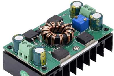
Printed Circuit Boards (PCBs) are the backbone of modern electronics, found in everything from smartphones to industrial machinery. Over time, PCBs can suffer damage due to electrical failures, physical stress, environmental factors, or manufacturing defects. PCB repair is a crucial skill for electronics technicians, engineers, and hobbyists, as it can save costs and extend the lifespan of electronic devices.
This article explores common PCB defects, diagnostic techniques, repair methods, essential tools, and best practices for successful PCB restoration.
Common PCB Defects
Before attempting repairs, it’s essential to identify the type of damage. Common PCB issues include:
1. Physical Damage
- Cracked or Broken Traces: Caused by mechanical stress, bending, or impact.
- Delamination: Separation of PCB layers due to heat or moisture exposure.
- Damaged Pads or Vias: Lifted or broken connection points from excessive soldering or force.
2. Electrical Failures
- Short Circuits: Caused by solder bridges, conductive debris, or damaged components.
- Open Circuits: Broken connections due to corrosion or trace fractures.
- Component Failures: Burnt-out resistors, capacitors, or ICs from overvoltage or overheating.
3. Environmental Damage
- Corrosion: Due to moisture, oxidation, or chemical exposure.
- Thermal Stress: Repeated heating/cooling cycles weaken solder joints.
- Contamination: Dust, flux residue, or metallic debris causing leakage or shorts.
Diagnostic Techniques
Accurate diagnosis is critical before attempting repairs. Common diagnostic methods include:
1. Visual Inspection
- Use a magnifying glass or microscope to check for burnt components, cracked traces, or solder defects.
- Look for discoloration (e.g., brown spots indicate overheating).
2. Multimeter Testing
- Continuity Test: Checks for broken traces or open circuits.
- Resistance Measurement: Identifies shorted or failed components.
- Voltage Testing: Verifies power delivery across circuits.
3. Thermal Imaging
- Infrared cameras detect overheating components, indicating potential shorts or failing parts.
4. Advanced Tools
- Oscilloscope: Analyzes signal integrity in high-frequency circuits.
- X-ray Inspection: Reveals hidden defects in multi-layer PCBs.
PCB Repair Techniques
Once the issue is identified, appropriate repair methods can be applied.
1. Trace Repair
Broken traces can be fixed by:
- Jumper Wires: Soldering thin enamel-coated wires to bypass damaged traces.
- Conductive Ink: Using silver-based ink to redraw broken traces.
- Copper Tape: Applying adhesive copper strips for temporary fixes.
2. Pad and Via Repair
Lifted pads or vias can be restored by:
- Epoxy Reinforcement: Securing loose pads with adhesive.
- Solder Bridges: Creating new connections with solder.
- Via Replacement: Using conductive paste or small copper rivets.
3. Solder Joint Repair
- Cold Joints: Reflow solder to ensure proper bonding.
- Cracked Joints: Remove old solder and reapply fresh solder.
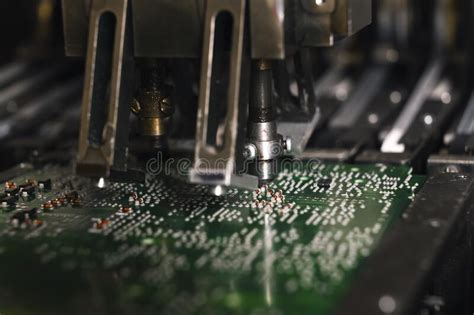
4. Component Replacement
- Desolder faulty components using a soldering iron, hot air gun, or desoldering pump.
- Install new components, ensuring correct polarity and alignment.
5. Corrosion Cleaning
- Use isopropyl alcohol (IPA) and a soft brush to clean corroded areas.
- For severe corrosion, lightly sand with fine-grit sandpaper.
6. PCB Delamination Repair
- Apply epoxy resin to bond separated layers.
- Clamp and cure under controlled heat.
Essential Tools for PCB Repair
A well-equipped workspace ensures efficient repairs:
| Tool | Purpose |
|---|---|
| Soldering Iron | Component soldering/desoldering |
| Hot Air Rework Station | SMD component removal |
| Multimeter | Continuity, voltage, resistance checks |
| Magnifying Glass/Microscope | Visual inspection |
| Copper Wire/Jumper Wires | Trace repairs |
| Conductive Epoxy/Silver Ink | Alternative trace repair |
| Isopropyl Alcohol | Cleaning flux and corrosion |
| Precision Tweezers | Handling small components |
| Oscilloscope | Signal analysis |
| PCB Clamps | Securing boards during repair |
Best Practices for PCB Repair
To ensure successful and long-lasting repairs:
- Work in a Clean, Static-Free Environment
- Use an anti-static mat and wrist strap to prevent ESD damage.
- Use Proper Soldering Techniques
- Avoid excessive heat to prevent pad lifting.
- Apply flux for better solder flow.
- Test Before and After Repairs
- Verify faults before starting and confirm fixes afterward.
- Document Repairs
- Note changes made for future troubleshooting.
- Avoid Over-repairing
- If a PCB is severely damaged, consider replacement instead of extensive fixes.
Conclusion
PCB repair is a valuable skill that can save time, money, and electronic waste. By understanding common defects, using proper diagnostic tools, and applying appropriate repair techniques, technicians can restore functionality to damaged boards. Whether repairing consumer electronics, industrial controls, or prototype circuits, following best practices ensures reliable and durable fixes.
As PCBs continue to evolve with higher complexity, staying updated with repair methodologies and tools will remain essential for electronics professionals and enthusiasts alike.