Prototype circuit board
Designing Your First Prototype Circuit Board: A Beginner’s Guide
Designing your first prototype circuit board can be an exhilarating yet daunting task. As a beginner, it is essential to understand the fundamental principles and steps involved in creating a functional and efficient prototype.
The process begins with a clear understanding of the circuit’s purpose and the components required to achieve the desired functionality.
This initial phase, often referred to as the conceptual design stage, involves sketching out the circuit on paper or using specialized software to visualize the connections and layout.
Once the conceptual design is in place, the next step is to select the appropriate components.
This involves choosing resistors, capacitors, transistors, and other electronic elements that match the specifications of your design. It is crucial to consider the electrical characteristics of each component, such as voltage ratings, current capacity, and tolerance levels, to ensure compatibility and reliability. Additionally, sourcing components from reputable suppliers can help avoid issues related to quality and performance.
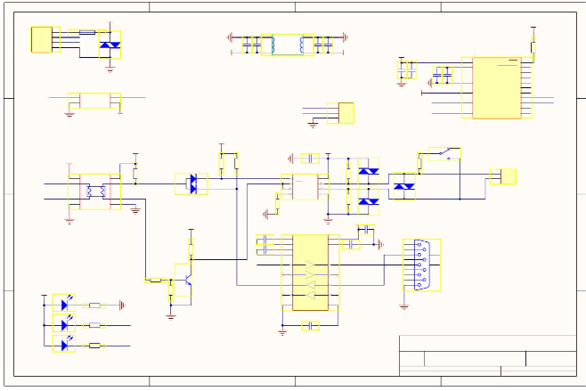
With the components selected, the focus shifts to creating a schematic diagram.
This diagram serves as a blueprint for your circuit, detailing the connections between components and providing a clear visual representation of the design. Schematic capture software can be particularly useful in this stage, offering tools to draw and simulate the circuit before moving on to the physical layout. Ensuring accuracy in the schematic is vital, as errors at this stage can lead to significant issues during the prototyping phase.
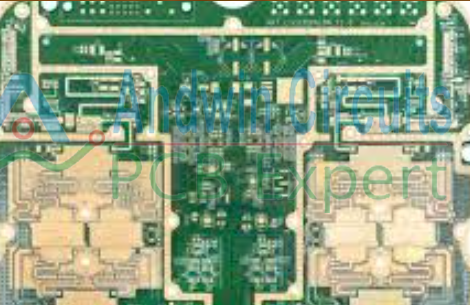
Transitioning from the schematic to the physical layout involves designing the actual circuit board.
This process, known as PCB (Printed Circuit Board) layout design, requires careful consideration of component placement, trace routing, and layer management. Effective PCB design minimizes signal interference, reduces noise, and ensures efficient power distribution. Utilizing PCB design software can greatly aid in this process, providing features such as auto-routing and design rule checks to streamline the layout.
After finalizing the PCB layout, the next step is to generate the necessary files for manufacturing.
These files, commonly referred to as Gerber files, contain detailed information about the board’s layers, including copper traces, solder masks, and silkscreen layers. Submitting these files to a PCB manufacturer will result in the production of your prototype circuit board. It is advisable to choose a manufacturer with a good track record and the capability to meet your specific requirements, such as board thickness, material type, and surface finish.
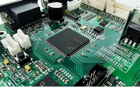
Upon receiving the manufactured PCB, the assembly process begins.
This involves soldering the components onto the board according to the layout design. Precision and attention to detail are crucial during this stage to avoid issues such as cold solder joints or component misalignment. Utilizing tools like soldering irons, tweezers, and magnifying glasses can enhance the accuracy of the assembly process.
Finally, testing and debugging the assembled prototype is essential to ensure it functions as intended.
This involves powering up the circuit and using testing equipment such as multimeters, oscilloscopes, and logic analyzers to verify the performance of each component and the overall circuit. Identifying and rectifying any issues at this stage is critical to achieving a reliable and functional prototype.
In conclusion, designing your first prototype circuit board requires a methodical approach, attention to detail, and a solid understanding of electronic principles. By following these steps and utilizing the appropriate tools and resources, you can successfully create a prototype that meets your design objectives and paves the way for further development and refinement.
Top Tools And Software For Prototype Circuit Board Development
Developing a prototype circuit board is a critical step in the process of bringing an electronic product from concept to reality. This phase involves designing, testing, and refining the circuit to ensure it meets the desired specifications and functions correctly. To achieve this, engineers and designers rely on a variety of tools and software that streamline the development process, enhance accuracy, and reduce the time required to move from design to production. Understanding the top tools and software available for prototype circuit board development is essential for anyone involved in this field.
One of the most widely used software tools for circuit board design is Altium Designer.
This comprehensive suite offers a range of features that facilitate schematic capture, PCB layout, and even 3D visualization of the board. Altium Designer’s integrated environment allows for seamless transitions between different stages of the design process, ensuring that changes made in one area are automatically reflected in others. This level of integration helps to minimize errors and improve overall design efficiency.
In addition to Altium Designer, Eagle PCB is another popular choice among engineers.
Known for its user-friendly interface and robust feature set, Eagle PCB provides tools for schematic design, board layout, and even autorouting. The software’s extensive library of components and parts makes it easier for designers to find the exact elements they need for their projects. Furthermore, Eagle PCB’s compatibility with various operating systems and its ability to handle complex designs make it a versatile option for prototype circuit board development.
For those seeking an open-source alternative, KiCad is an excellent option.
KiCad offers a suite of programs for schematic capture, PCB layout, and Gerber file generation, which are essential for manufacturing the circuit board. The software’s open-source nature means that it is continually being improved by a community of developers, ensuring that it remains up-to-date with the latest advancements in the field. Additionally, KiCad’s extensive documentation and active user community provide valuable support for both novice and experienced designers.
Beyond software, hardware tools play a crucial role in the development of prototype circuit boards.
One such tool is the oscilloscope, which allows engineers to observe the electrical signals within a circuit. By providing real-time data on voltage, frequency, and waveform characteristics, oscilloscopes help designers identify and troubleshoot issues that may arise during testing. High-quality oscilloscopes, such as those from Tektronix or Keysight Technologies, offer advanced features like deep memory and high sampling rates, which are essential for accurate signal analysis.
Another indispensable hardware tool is the multimeter.
This versatile instrument measures voltage, current, and resistance, providing essential data for verifying the functionality of a circuit. Modern digital multimeters, such as those from Fluke or Agilent, offer high precision and reliability, making them a staple in any engineer’s toolkit. Additionally, some multimeters come with advanced features like data logging and connectivity options, further enhancing their utility in prototype development.
In conclusion, the development of a prototype circuit board requires a combination of sophisticated software and reliable hardware tools. Altium Designer, Eagle PCB, and KiCad are among the top software options, each offering unique features that cater to different needs and preferences. Meanwhile, essential hardware tools like oscilloscopes and multimeters provide the necessary data and insights to ensure that the circuit functions as intended. By leveraging these tools and software, engineers can streamline the development process, reduce errors, and ultimately bring their electronic products to market more efficiently.
Common Mistakes To Avoid When Creating A Prototype Circuit Board
Creating a prototype circuit board is a critical step in the development of any electronic device. However, this process is fraught with potential pitfalls that can lead to costly delays and suboptimal performance. One common mistake is inadequate planning. Before even beginning the design, it is essential to have a clear understanding of the project requirements and constraints. This includes knowing the specifications of the components, the power requirements, and the intended use of the final product. Without a well-thought-out plan, designers may find themselves making frequent revisions, which can be both time-consuming and expensive.
Another frequent error is poor component selection.
Choosing the wrong components can lead to a host of issues, including incompatibility, excessive power consumption, and even failure of the circuit. It is crucial to thoroughly research and select components that meet the necessary specifications and are compatible with each other. Additionally, designers should consider the availability and cost of components, as some may be difficult to source or prohibitively expensive.
Transitioning to the layout phase, improper placement of components is a mistake that can severely impact the performance of the circuit board.
Components should be placed in a manner that minimizes signal interference and optimizes the flow of current. For instance, placing high-frequency components too close to each other can result in electromagnetic interference, which can degrade the performance of the circuit. Similarly, power and ground traces should be carefully designed to ensure stable and efficient power distribution.
Moreover, neglecting thermal management is another common oversight.
Electronic components generate heat, and if this heat is not properly managed, it can lead to overheating and failure of the circuit. Designers should incorporate adequate heat sinks, thermal vias, and consider the placement of components to ensure efficient heat dissipation. Failing to address thermal management can result in reduced lifespan and reliability of the prototype circuit board.
In addition to these technical aspects, overlooking the importance of thorough testing is a critical mistake.
Once the prototype circuit board is assembled, it is imperative to conduct comprehensive testing to identify and rectify any issues. This includes functional testing, stress testing, and environmental testing to ensure the circuit performs reliably under various conditions. Skipping or rushing through the testing phase can result in undetected flaws that may cause the final product to fail in the field.
Furthermore, inadequate documentation is a mistake that can complicate the development process.
Proper documentation of the design, including schematics, layout files, and a bill of materials, is essential for troubleshooting and future revisions. Without detailed documentation, it can be challenging to identify the source of issues or make necessary modifications.
Lastly, failing to consider manufacturability can lead to significant problems when transitioning from prototype to production. Designers should keep in mind the capabilities and limitations of the manufacturing process, including tolerances, assembly techniques, and testing procedures. Designing a prototype that is difficult or costly to manufacture can result in delays and increased production costs.
In conclusion, creating a prototype circuit board involves careful planning, meticulous component selection, strategic layout, effective thermal management, thorough testing, comprehensive documentation, and consideration of manufacturability. By avoiding these common mistakes, designers can enhance the reliability, performance, and cost-effectiveness of their prototype circuit boards, ultimately leading to a successful final product.

The Future Of Prototype Circuit Boards: Trends And Innovations
The future of prototype circuit boards is poised for significant advancements, driven by emerging trends and innovative technologies. As the backbone of modern electronics, prototype circuit boards are essential for testing and validating new designs before mass production. The rapid pace of technological development necessitates continuous improvements in this field, ensuring that prototype circuit boards remain at the forefront of innovation.
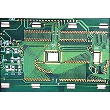
One of the most notable trends in prototype circuit boards is the increasing miniaturization of electronic components.
As devices become smaller and more powerful, the demand for compact and efficient circuit boards has surged. This trend is particularly evident in the consumer electronics industry, where smartphones, wearables, and other portable devices require highly integrated and densely packed circuit boards. To meet these demands, manufacturers are leveraging advanced fabrication techniques such as surface-mount technology (SMT) and multi-layered PCB designs. These methods allow for the integration of more components in a smaller footprint, enhancing the overall performance and functionality of the devices.
In addition to miniaturization, the rise of the Internet of Things (IoT) has significantly influenced the development of prototype circuit boards.
IoT devices, which connect and communicate over the internet, require specialized circuit boards that can handle wireless communication, data processing, and power management. Consequently, there is a growing emphasis on designing circuit boards that are not only compact but also energy-efficient and capable of supporting various communication protocols.
Innovations in materials science, such as the use of flexible and stretchable substrates, are also playing a crucial role in the evolution of IoT-compatible circuit boards. These materials enable the creation of flexible and wearable electronics, opening up new possibilities for applications in healthcare, fitness, and beyond.
Another key trend shaping the future of prototype circuit boards is the integration of artificial intelligence (AI) and machine learning (ML) technologies.
AI and ML are being increasingly utilized in the design and testing phases of circuit board development. By employing sophisticated algorithms, designers can optimize circuit layouts, predict potential issues, and streamline the prototyping process. This not only reduces the time and cost associated with developing new circuit boards but also enhances their reliability and performance. Furthermore, AI-driven tools can assist in the automated inspection and quality control of prototype circuit boards, ensuring that they meet stringent industry standards.
The advent of additive manufacturing, commonly known as 3D printing, is also revolutionizing the prototype circuit board industry.
3D printing allows for the rapid and cost-effective production of custom circuit board designs, enabling engineers to quickly iterate and refine their prototypes. This technology is particularly beneficial for small-scale production runs and specialized applications where traditional manufacturing methods may be prohibitively expensive or time-consuming. As 3D printing technology continues to advance, it is expected to play an increasingly prominent role in the prototyping and manufacturing of circuit boards.
Moreover, the push towards sustainability and environmental responsibility is influencing the development of prototype circuit boards.
Manufacturers are exploring eco-friendly materials and processes to reduce the environmental impact of circuit board production. This includes the use of biodegradable substrates, lead-free solder, and energy-efficient manufacturing techniques. By adopting sustainable practices, the industry aims to minimize waste and reduce its carbon footprint, contributing to a more sustainable future.
In conclusion, the future of prototype circuit boards is being shaped by a confluence of trends and innovations. Miniaturization, IoT integration, AI and ML advancements, 3D printing, and sustainability are all driving the evolution of this critical technology. As these trends continue to develop, prototype circuit boards will become more sophisticated, efficient, and environmentally friendly, paving the way for the next generation of electronic device