Quality Basic Requirements for PCB Circuit Boards
Introduction
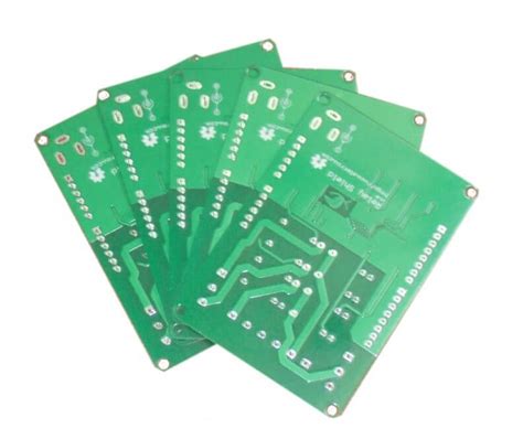
Printed Circuit Boards (PCBs) are essential components in modern electronic devices, serving as the foundation for mounting and interconnecting electronic components. The quality of a PCB directly affects the performance, reliability, and longevity of the final product. Therefore, understanding the fundamental quality requirements for PCBs is crucial for manufacturers, designers, and engineers.
This article outlines the key quality requirements for PCB circuit boards, covering material selection, design specifications, manufacturing processes, testing methods, and industry standards. By adhering to these requirements, manufacturers can ensure high-quality PCBs that meet the demands of various applications, from consumer electronics to aerospace and medical devices.
1. Material Quality Requirements
The materials used in PCB manufacturing significantly impact the board’s performance. Key considerations include:
1.1 Substrate Material
- FR-4: The most common substrate, made of fiberglass and epoxy resin, offers good mechanical strength and electrical insulation.
- High-Frequency Materials: For RF and microwave applications, materials like PTFE (Teflon) or ceramic-filled laminates are used to minimize signal loss.
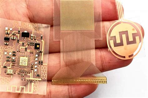
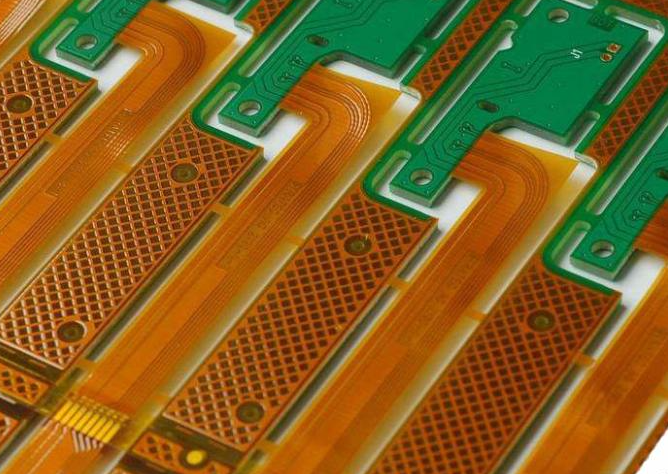
- Flexible PCB Materials: Polyimide or PET films are used for flexible PCBs, providing bendability and durability.
1.2 Copper Foil Quality
- Thickness: Typically ranges from 0.5 oz to 3 oz per square foot, depending on current-carrying requirements.
- Purity: High-purity electrolytic or rolled copper ensures low resistance and good conductivity.
- Surface Treatment: Proper adhesion to the substrate is critical to prevent delamination.
1.3 Solder Mask and Silkscreen
- Solder Mask: Must provide insulation, corrosion resistance, and proper adhesion. Common types include liquid photoimageable (LPI) and dry film solder masks.
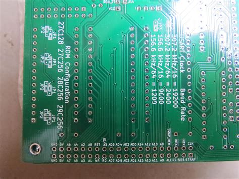
- Silkscreen: Used for component labeling; must be legible and resistant to abrasion and chemicals.
2. Design and Layout Quality Requirements
A well-designed PCB ensures signal integrity, thermal management, and manufacturability. Key factors include:
2.1 Trace Width and Spacing
- Current Carrying Capacity: Traces must be wide enough to handle expected current without overheating.
- Signal Integrity: Proper spacing minimizes crosstalk and electromagnetic interference (EMI).
2.2 Via Design
- Through-Hole, Blind, and Buried Vias: Must be properly sized and plated to ensure reliable connections.
- Microvias: Used in high-density interconnect (HDI) PCBs for fine-pitch components.
2.3 Thermal Management
- Heat Dissipation: Copper pours, thermal vias, and heatsinks help manage heat in high-power circuits.
- Thermal Expansion Matching: Materials should have similar coefficients of thermal expansion (CTE) to prevent warping.
2.4 Component Placement
- Manufacturability: Components should be placed to facilitate automated assembly (e.g., avoiding tombstoning in SMT).
- Signal Path Optimization: High-speed signals should have minimal length and avoid sharp bends.
3. Manufacturing Process Quality Requirements
The PCB fabrication process must adhere to strict standards to ensure reliability.
3.1 Etching and Plating
- Precision Etching: Over-etching or under-etching can cause open or short circuits.
- Copper Plating: Uniform thickness ensures consistent conductivity and mechanical strength.
3.2 Drilling and Hole Quality
- Hole Wall Smoothness: Rough holes can lead to poor plating and weak connections.
- Registration Accuracy: Misaligned holes can cause assembly issues.
3.3 Lamination
- Delamination Prevention: Proper pressure and temperature during lamination ensure layer bonding.
- Void-Free Construction: Air bubbles or resin voids weaken the PCB structure.
3.4 Surface Finishes
- HASL (Hot Air Solder Leveling): Provides good solderability but may not be suitable for fine-pitch components.
- ENIG (Electroless Nickel Immersion Gold): Offers a flat surface for fine-pitch components and good corrosion resistance.
- OSP (Organic Solderability Preservative): A cost-effective option but has limited shelf life.
4. Testing and Inspection Requirements
Quality control is critical to ensure defect-free PCBs. Common testing methods include:
4.1 Electrical Testing
- Continuity Testing: Ensures no open circuits.
- Insulation Resistance Testing: Verifies no short circuits between traces.
4.2 Automated Optical Inspection (AOI)
- Detects defects such as scratches, misaligned traces, and solder mask errors.
4.3 X-Ray Inspection
- Used for checking internal layers, via integrity, and BGA (Ball Grid Array) solder joints.
4.4 Environmental and Reliability Testing
- Thermal Cycling: Tests resistance to temperature fluctuations.
- Humidity Testing: Ensures performance in high-moisture environments.
- Vibration and Shock Testing: Validates durability in mechanical stress conditions.
5. Compliance with Industry Standards
PCBs must meet relevant industry standards, such as:
- IPC-A-600: Acceptability of Printed Boards
- IPC-6012: Qualification and Performance Specification for Rigid PCBs
- UL Certification: Ensures safety for consumer and industrial applications.
- RoHS & REACH Compliance: Restricts hazardous substances in electronic products.
Conclusion
The quality of a PCB depends on multiple factors, including material selection, design precision, manufacturing processes, and rigorous testing. By adhering to these fundamental requirements, manufacturers can produce reliable, high-performance PCBs that meet the demands of modern electronics. Continuous advancements in PCB technology, such as HDI and flexible circuits, further emphasize the importance of maintaining stringent quality standards.
Investing in high-quality PCBs not only enhances product performance but also reduces long-term costs by minimizing failures and ensuring compliance with industry regulations. Whether for consumer electronics, automotive systems, or aerospace applications, a well-manufactured PCB is the backbone of electronic reliability.

