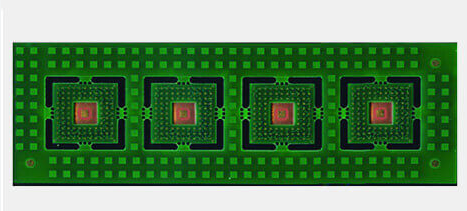
Rogers pcb prototype
Benefits Of Using Rogers PCB Prototypes In High-Frequency Applications
Rogers PCB prototypes have become increasingly popular in high-frequency applications due to their exceptional performance characteristics and reliability. These specialized printed circuit boards (PCBs) are crafted from Rogers Corporation’s advanced materials, which are specifically designed to meet the stringent demands of high-frequency and high-speed electronic circuits.
One of the primary benefits of using Rogers PCB prototypes in such applications is their superior dielectric properties.
Unlike traditional FR-4 materials, Rogers materials exhibit low dielectric constant (Dk) and low dissipation factor (Df), which are crucial for maintaining signal integrity and minimizing signal loss at high frequencies. This ensures that the electronic signals can travel through the circuit with minimal degradation, thereby enhancing the overall performance of the device.
In addition to their excellent dielectric properties, Rogers PCB prototypes offer remarkable thermal management capabilities.
High-frequency applications often generate significant amounts of heat, which can adversely affect the performance and longevity of electronic components. Rogers materials are engineered to provide efficient heat dissipation, thereby preventing overheating and ensuring stable operation. This thermal stability is particularly important in applications such as RF and microwave communication systems, where consistent performance is critical.
Furthermore, Rogers PCB prototypes are known for their dimensional stability and mechanical robustness.
These attributes are essential for maintaining the precise alignment and spacing of circuit traces, which is vital for high-frequency signal transmission. The dimensional stability of Rogers materials ensures that the PCB maintains its structural integrity even under varying environmental conditions, such as changes in temperature and humidity. This reliability is a key factor in applications where precision and consistency are paramount.
Another significant advantage of using Rogers PCB prototypes is their compatibility with advanced manufacturing processes.
Rogers materials can be easily integrated into various fabrication techniques, including multilayer PCB construction and high-density interconnect (HDI) technology. This versatility allows designers to create complex and compact circuit layouts that meet the specific requirements of high-frequency applications. Additionally, the ease of processing Rogers materials can lead to reduced production times and costs, making them an attractive option for both prototyping and large-scale manufacturing.
Moreover, Rogers PCB prototypes offer excellent signal integrity and reduced electromagnetic interference (EMI).
High-frequency circuits are particularly susceptible to EMI, which can degrade signal quality and lead to performance issues. The low-loss characteristics of Rogers materials help to minimize EMI, ensuring that the signals remain clean and undistorted. This is especially important in applications such as radar systems, satellite communications, and wireless networks, where maintaining signal clarity is crucial.
In conclusion, the benefits of using Rogers PCB prototypes in high-frequency applications are manifold. Their superior dielectric properties, thermal management capabilities, dimensional stability, and mechanical robustness make them an ideal choice for demanding electronic circuits. Additionally, their compatibility with advanced manufacturing processes and ability to maintain signal integrity further enhance their appeal. As high-frequency applications continue to evolve and become more complex, the use of Rogers PCB prototypes is likely to become even more prevalent, providing designers with the tools they need to achieve optimal performance and reliability in their electronic devices.
Step-By-Step Guide To Designing A Rogers PCB Prototype
Designing a Rogers PCB prototype involves a meticulous process that requires a deep understanding of both the materials and the steps involved. Rogers PCBs are known for their high-frequency performance and are often used in applications such as RF, microwave, and high-speed digital circuits. To begin with, the selection of the appropriate Rogers material is crucial. Rogers Corporation offers a variety of laminates, each with specific properties tailored to different applications. For instance, Rogers RO4000 series is commonly used for RF applications due to its low dielectric loss and stable electrical properties.
Once the material is selected, the next step is to design the PCB layout.
This involves using specialized software such as Altium Designer, Eagle, or KiCad. The layout design must consider the unique properties of Rogers materials, such as their dielectric constant and thermal conductivity. It is essential to ensure that the trace widths, spacing, and layer stack-up are optimized for the intended application. During this phase, it is also important to incorporate design rules that account for the material’s characteristics, such as controlled impedance and minimal signal loss.
Following the layout design, the next step is to generate the Gerber files.
These files are the standard format for PCB manufacturing and contain all the necessary information for the fabrication process. It is imperative to double-check the Gerber files for any errors or inconsistencies, as these can lead to costly mistakes during manufacturing. Additionally, a design rule check (DRC) should be performed to ensure that the design adheres to the manufacturing capabilities and constraints.
After generating the Gerber files, the next phase is the fabrication of the PCB.
This involves several steps, including material preparation, lamination, drilling, and plating. Rogers materials require specific handling and processing techniques due to their unique properties. For instance, the lamination process must be carefully controlled to avoid any defects or delamination. Similarly, the drilling process must be optimized to prevent any damage to the material or the plated through-holes.
Once the PCB is fabricated, the next step is to assemble the components.
This involves placing and soldering the components onto the PCB. Given the high-frequency nature of Rogers PCBs, it is essential to use precise and reliable assembly techniques. Surface mount technology (SMT) is commonly used for this purpose, as it allows for accurate placement and soldering of components. Additionally, it is important to ensure that the solder joints are of high quality to avoid any signal integrity issues.
Following assembly, the final step is to test the PCB prototype.
This involves performing various tests to ensure that the PCB meets the required specifications and performance criteria. For high-frequency applications, this may include testing for signal integrity, impedance matching, and thermal performance. Any issues identified during testing must be addressed and rectified before proceeding to mass production.
In conclusion, designing a Rogers PCB prototype is a complex process that requires careful consideration of the material properties and meticulous attention to detail at each step. From selecting the appropriate material and designing the layout to fabricating, assembling, and testing the PCB, each phase plays a critical role in ensuring the success of the final product. By following a systematic and thorough approach, it is possible to achieve a high-performance Rogers PCB prototype that meets the stringent requirements of advanced electronic applications.
Comparing Rogers PCB Prototypes To Traditional FR4 Boards
When comparing Rogers PCB prototypes to traditional FR4 boards, it is essential to understand the fundamental differences between these two materials and their respective applications. Rogers PCBs, known for their high-frequency performance and superior thermal management, are often favored in advanced electronic applications. In contrast, FR4 boards, made from woven glass-epoxy laminate, are widely used in general-purpose electronic circuits due to their cost-effectiveness and satisfactory performance in standard applications.
One of the primary distinctions between Rogers PCBs and FR4 boards lies in their dielectric properties.
Rogers materials exhibit a lower dielectric constant (Dk) and dissipation factor (Df) compared to FR4. This characteristic is crucial for high-frequency applications, as it minimizes signal loss and ensures signal integrity. Consequently, Rogers PCBs are commonly employed in RF (radio frequency) and microwave circuits, where maintaining signal fidelity is paramount. On the other hand, FR4 boards, with their higher dielectric constant, are suitable for lower-frequency applications where such stringent requirements are not necessary.
Thermal management is another critical area where Rogers PCBs outperform traditional FR4 boards.
Rogers materials possess superior thermal conductivity, which allows for better heat dissipation. This property is particularly advantageous in high-power applications, where excessive heat can lead to component failure and reduced reliability. By effectively managing heat, Rogers PCBs enhance the longevity and performance of electronic devices. In contrast, FR4 boards, with their lower thermal conductivity, may struggle to dissipate heat efficiently, potentially leading to thermal issues in demanding applications.
Moreover, the mechanical properties of Rogers PCBs contribute to their suitability for specific applications.
Rogers materials offer better dimensional stability and lower moisture absorption compared to FR4. This stability ensures that the PCB maintains its structural integrity under varying environmental conditions, which is critical for applications exposed to harsh environments or significant temperature fluctuations. Conversely, FR4 boards, while generally robust, may experience dimensional changes and moisture absorption, potentially affecting their performance and reliability in certain scenarios.
Despite these advantages, it is important to consider the cost implications when choosing between Rogers PCBs and FR4 boards.
Rogers materials are typically more expensive than FR4, which can be a significant factor in large-scale production or cost-sensitive projects. Therefore, the decision to use Rogers PCBs should be justified by the specific performance requirements of the application. For instance, in high-frequency or high-power applications where the benefits of Rogers materials are indispensable, the higher cost may be warranted. Conversely, for standard applications where the performance of FR4 is adequate, the cost savings offered by FR4 boards make them a more practical choice.
In addition to cost, the manufacturing process for Rogers PCBs can be more complex compared to FR4 boards.
The specialized materials and techniques required for Rogers PCBs may necessitate additional expertise and equipment, potentially leading to longer lead times and higher production costs. However, for applications that demand the unique properties of Rogers materials, these challenges are often outweighed by the performance benefits.
In conclusion, the choice between Rogers PCB prototypes and traditional FR4 boards hinges on a careful evaluation of the application’s specific requirements. While Rogers PCBs offer superior dielectric properties, thermal management, and mechanical stability, they come at a higher cost and may involve more complex manufacturing processes. Conversely, FR4 boards provide a cost-effective solution for general-purpose applications, albeit with some limitations in high-frequency and high-power scenarios. By understanding these differences, engineers and designers can make informed decisions that optimize performance, reliability, and cost-efficiency in their electronic designs.
Common Challenges And Solutions In Rogers PCB Prototyping
Rogers PCB prototyping is a critical process in the development of high-frequency and high-performance electronic circuits. However, it is not without its challenges. One of the most common issues encountered in Rogers PCB prototyping is material handling. Rogers materials, known for their excellent dielectric properties and thermal stability, can be quite sensitive to environmental conditions. For instance, moisture absorption can significantly affect the performance of the PCB. To mitigate this, it is essential to store Rogers materials in a controlled environment with low humidity and to handle them with care during the manufacturing process.
Another significant challenge is the precise control of the etching process.
Rogers PCBs often require very fine features and tight tolerances, which can be difficult to achieve with standard etching techniques. Inaccurate etching can lead to issues such as signal loss and impedance mismatches. To address this, advanced etching techniques and equipment are often employed. Additionally, regular calibration and maintenance of etching equipment are crucial to ensure consistent results.
Thermal management is also a critical concern in Rogers PCB prototyping.
The high-frequency applications for which Rogers materials are typically used generate substantial heat, which can affect the performance and reliability of the PCB. Effective thermal management strategies, such as the use of thermal vias, heat sinks, and proper PCB layout design, are essential to dissipate heat efficiently. Moreover, selecting the appropriate Rogers material with the right thermal conductivity properties can significantly enhance thermal performance.
The complexity of multilayer Rogers PCBs presents another set of challenges.
Ensuring proper layer alignment and registration is vital to avoid issues such as short circuits and signal integrity problems. Advanced fabrication techniques, such as laser drilling and precision lamination, are often required to achieve the necessary accuracy. Furthermore, thorough inspection and testing at each stage of the manufacturing process can help identify and rectify alignment issues early on.
Signal integrity is a paramount concern in high-frequency applications, and Rogers PCBs are no exception.
Factors such as trace width, spacing, and the dielectric constant of the material can all impact signal integrity. To address these issues, careful design and simulation are necessary. Utilizing advanced design software that can model high-frequency behavior and predict potential issues can be invaluable. Additionally, following best practices for PCB layout, such as maintaining consistent trace widths and minimizing signal path lengths, can help preserve signal integrity.
Cost is another factor that cannot be overlooked in Rogers PCB prototyping.
The specialized materials and advanced manufacturing techniques required for Rogers PCBs can be more expensive than those for standard PCBs. To manage costs effectively, it is important to optimize the design for manufacturability. This includes minimizing the number of layers, using standard board sizes, and avoiding overly complex features that can drive up production costs. Collaborating closely with the PCB manufacturer during the design phase can also help identify cost-saving opportunities without compromising performance.
In conclusion, while Rogers PCB prototyping presents several challenges, these can be effectively managed through careful planning, advanced manufacturing techniques, and close collaboration with experienced PCB manufacturers. By addressing issues such as material handling, etching precision, thermal management, multilayer complexity, signal integrity, and cost, it is possible to achieve high-performance Rogers PCBs that meet the demanding requirements of high-frequency applications.


