Semi flexible pcbselecting pcb materials for high-frequency applications
Understanding Dielectric Constant in High-Frequency PCB Materials
When selecting printed circuit board (PCB) materials for high-frequency applications, understanding the dielectric constant (Dk) is crucial. The dielectric constant, also known as relative permittivity, measures a material’s ability to store electrical energy in an electric field. This property significantly impacts signal integrity, propagation speed, and overall performance of high-frequency circuits. Therefore, a comprehensive grasp of Dk is essential for engineers and designers aiming to optimize their PCB designs for high-frequency applications.
To begin with, the dielectric constant influences the impedance of transmission lines on the PCB.
Impedance control is vital in high-frequency circuits to ensure signal integrity and minimize reflections. Materials with a stable and low Dk are preferred because they provide consistent impedance, which is critical for maintaining signal fidelity. For instance, materials like PTFE (Polytetrafluoroethylene) and certain ceramic-filled laminates exhibit low and stable Dk values, making them suitable for high-frequency applications.
Moreover, the dielectric constant affects the signal propagation speed through the PCB material.
A lower Dk results in a higher signal propagation speed, which is advantageous for high-frequency circuits where timing and synchronization are paramount. Faster signal propagation reduces latency and enhances the overall performance of the circuit. Consequently, selecting materials with an appropriate Dk can lead to significant improvements in the speed and efficiency of high-frequency electronic devices.
In addition to impedance and signal propagation, the dielectric constant also impacts the loss tangent or dissipation factor of the PCB material.
The loss tangent measures the energy loss as the signal propagates through the material. A lower Dk generally correlates with a lower loss tangent, which is desirable for high-frequency applications. Lower energy loss translates to reduced signal attenuation, ensuring that the signal remains strong and clear over longer distances. This is particularly important in applications such as RF (Radio Frequency) and microwave communications, where signal strength and clarity are critical.
Furthermore, the dielectric constant can vary with frequency, temperature, and humidity.
High-frequency applications often operate in environments where these factors fluctuate, making it essential to choose materials with a stable Dk across a range of conditions. Materials like Rogers RO3000 series and Taconic RF-35 are known for their stable dielectric properties over a wide frequency range and varying environmental conditions. This stability ensures consistent performance and reliability of the high-frequency circuits.
It is also important to consider the manufacturability and cost of PCB materials with the desired dielectric properties.
While materials with low and stable Dk values offer superior performance, they can be more challenging to process and may come at a higher cost. Balancing performance requirements with manufacturability and budget constraints is a critical aspect of the material selection process. Collaborating with material suppliers and PCB manufacturers can provide valuable insights into the trade-offs and help in making informed decisions.
In conclusion, understanding the dielectric constant is fundamental when selecting PCB materials for high-frequency applications. The Dk influences impedance control, signal propagation speed, and energy loss, all of which are critical for the performance of high-frequency circuits. By choosing materials with appropriate and stable dielectric properties, engineers can enhance signal integrity, reduce latency, and ensure reliable operation of their high-frequency electronic devices. Balancing these technical requirements with manufacturability and cost considerations will lead to optimal material selection and successful high-frequency PCB designs.
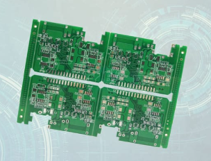
Importance of Low Loss Tangent in High-Frequency PCB Design
In the realm of high-frequency printed circuit board (PCB) design, the selection of appropriate materials is paramount to ensuring optimal performance. One critical parameter that designers must consider is the loss tangent, also known as the dissipation factor. The loss tangent is a measure of the dielectric material’s inherent energy loss when subjected to an alternating electric field. In high-frequency applications, minimizing this energy loss is crucial for maintaining signal integrity and achieving efficient operation.
To understand the importance of a low loss tangent, it is essential to recognize how high-frequency signals interact with PCB materials.
At elevated frequencies, signals tend to propagate through the dielectric material rather than just along the surface of the conductors. Consequently, the dielectric properties of the substrate become significantly influential. A high loss tangent indicates that the material will dissipate more energy as heat, leading to signal attenuation and potential distortion. This energy loss can degrade the performance of high-frequency circuits, resulting in reduced signal strength and increased noise.
Moreover, the loss tangent directly impacts the quality factor (Q-factor) of the PCB.
The Q-factor is a dimensionless parameter that describes the efficiency of a resonant circuit. A lower loss tangent contributes to a higher Q-factor, which is desirable for applications such as filters, oscillators, and antennas. These components rely on high Q-factors to achieve narrow bandwidths and stable frequency responses. Therefore, selecting a PCB material with a low loss tangent is essential for maintaining the integrity and performance of these high-frequency elements.
In addition to signal integrity and Q-factor considerations, thermal management is another critical aspect influenced by the loss tangent.
High-frequency circuits often generate substantial heat due to the rapid switching of signals. Materials with a high loss tangent exacerbate this issue by converting more electrical energy into heat. This not only affects the thermal stability of the PCB but also poses challenges for heat dissipation. Effective thermal management is vital to prevent overheating, which can lead to component failure and reduced reliability. By choosing materials with a low loss tangent, designers can mitigate excessive heat generation and enhance the overall thermal performance of the PCB.
Furthermore, the choice of PCB material with a low loss tangent can also impact the manufacturability and longevity of the circuit board.
Materials with high loss tangents may require more stringent manufacturing processes to ensure consistent performance. This can increase production costs and complexity. Additionally, high energy dissipation can accelerate material degradation over time, reducing the lifespan of the PCB. By opting for materials with low loss tangents, designers can achieve more reliable and durable high-frequency circuits, ultimately leading to cost savings and improved product longevity.
In conclusion, the importance of a low loss tangent in high-frequency PCB design cannot be overstated. It plays a crucial role in maintaining signal integrity, enhancing the Q-factor, managing thermal performance, and ensuring the manufacturability and longevity of the circuit board. As high-frequency applications continue to proliferate in various industries, from telecommunications to aerospace, the careful selection of PCB materials with low loss tangents will remain a fundamental consideration for designers aiming to achieve optimal performance and reliability in their high-frequency circuits.
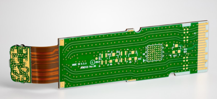
Thermal Management Considerations for High-Frequency PCBs
When selecting printed circuit board (PCB) materials for high-frequency applications, thermal management considerations play a crucial role in ensuring optimal performance and reliability. High-frequency circuits, often used in telecommunications, radar systems, and advanced computing, generate significant amounts of heat due to their rapid signal processing and high power densities. Consequently, effective thermal management is essential to prevent overheating, which can lead to signal degradation, component failure, and reduced lifespan of the PCB.
One of the primary factors to consider in thermal management is the thermal conductivity of the PCB material.
High-frequency PCBs typically require materials with high thermal conductivity to efficiently dissipate heat away from critical components. Materials such as ceramic-filled polytetrafluoroethylene (PTFE) and certain types of thermoset resins are often preferred due to their superior thermal properties. These materials facilitate the rapid transfer of heat, thereby maintaining the integrity of the signal and ensuring the stability of the circuit.
In addition to thermal conductivity, the coefficient of thermal expansion (CTE) is another critical parameter.
The CTE measures how much a material expands or contracts with temperature changes. Mismatched CTE values between the PCB substrate and the components can lead to mechanical stress, resulting in solder joint failures and potential circuit malfunctions. Therefore, selecting materials with a CTE that closely matches that of the components is vital for maintaining the mechanical integrity of the PCB under thermal cycling conditions.
Moreover, the dielectric properties of the PCB material must be considered in conjunction with thermal management.
High-frequency signals are highly sensitive to the dielectric constant (Dk) and dissipation factor (Df) of the substrate material. Materials with low Dk and Df values are preferred as they minimize signal loss and ensure efficient signal transmission. However, these materials must also possess adequate thermal stability to withstand the heat generated during operation. Balancing dielectric properties with thermal performance is a delicate task that requires careful material selection and design optimization.
Thermal vias and heat sinks are additional techniques employed to enhance thermal management in high-frequency PCBs.
Thermal vias are strategically placed through-holes that facilitate heat transfer from the surface of the PCB to the inner layers or to an external heat sink. These vias are often filled with conductive materials such as copper to maximize heat dissipation. Heat sinks, on the other hand, are external components attached to the PCB to absorb and dissipate heat away from critical areas. The integration of thermal vias and heat sinks into the PCB design can significantly improve thermal performance and ensure the longevity of the circuit.
Furthermore, the layout and design of the PCB itself can influence thermal management.
Proper component placement, adequate spacing, and the use of thermal relief pads can enhance heat dissipation and reduce thermal stress. For instance, placing high-power components away from sensitive signal traces can prevent thermal interference and maintain signal integrity. Additionally, employing thermal relief pads around solder joints can mitigate the risk of thermal damage during soldering processes.
In conclusion, selecting PCB materials for high-frequency applications necessitates a comprehensive understanding of thermal management considerations. High thermal conductivity, appropriate CTE, and favorable dielectric properties are essential attributes of suitable PCB materials. The integration of thermal vias, heat sinks, and thoughtful PCB design further enhances thermal performance. By meticulously addressing these factors, engineers can ensure the reliability, efficiency, and longevity of high-frequency PCBs, thereby meeting the demanding requirements of advanced electronic applications.
Comparing FR4 and Rogers Materials for High-Frequency Applications
When selecting printed circuit board (PCB) materials for high-frequency applications, engineers often find themselves comparing FR4 and Rogers materials. Both materials have distinct properties that make them suitable for different applications, and understanding these differences is crucial for making an informed decision.
FR4 is a widely used PCB material, known for its affordability and versatility.
It is composed of woven fiberglass cloth with an epoxy resin binder that is flame resistant. This material is highly favored in many standard electronic applications due to its mechanical strength, electrical insulation properties, and cost-effectiveness. However, when it comes to high-frequency applications, FR4’s limitations become apparent. The dielectric constant (Dk) of FR4 is relatively high and varies with frequency, which can lead to signal integrity issues. Additionally, FR4 has higher dielectric losses, which can result in significant signal attenuation at high frequencies.
In contrast, Rogers materials are specifically engineered for high-frequency applications.
These materials are known for their low dielectric constant and low loss tangent, which remain stable over a wide range of frequencies. This stability is crucial for maintaining signal integrity in high-frequency circuits. Rogers materials are typically composed of ceramic-filled hydrocarbon or PTFE (polytetrafluoroethylene) composites, which provide excellent electrical performance. The low dielectric constant of Rogers materials minimizes signal delay and dispersion, ensuring that high-frequency signals are transmitted with minimal loss and distortion.
Another important factor to consider is thermal management.
High-frequency applications often generate significant amounts of heat, and the PCB material must be able to dissipate this heat effectively to prevent damage to the components. FR4 has a lower thermal conductivity compared to Rogers materials, which can lead to overheating issues in high-frequency circuits. Rogers materials, on the other hand, offer better thermal management properties, allowing for more efficient heat dissipation and improved reliability of the circuit.
Moreover, the manufacturing process and material handling also differ between FR4 and Rogers materials.
FR4 is easier to process and handle due to its rigidity and well-established manufacturing techniques. This ease of processing translates to lower production costs and faster turnaround times. Conversely, Rogers materials can be more challenging to work with due to their softer and more flexible nature. Specialized equipment and techniques are often required to handle and process these materials, which can increase manufacturing complexity and cost.
Despite these challenges, the superior electrical performance of Rogers materials makes them the preferred choice for high-frequency applications such as RF (radio frequency) and microwave circuits, satellite communications, and advanced radar systems. The trade-off between cost and performance is a critical consideration, and engineers must weigh the benefits of improved signal integrity and thermal management against the higher material and manufacturing costs.
In conclusion, while FR4 remains a popular choice for many standard electronic applications due to its cost-effectiveness and ease of processing, it falls short in high-frequency applications where signal integrity and thermal management are paramount. Rogers materials, with their low dielectric constant, low loss tangent, and superior thermal properties, offer significant advantages for high-frequency circuits despite the higher costs and manufacturing challenges. Therefore, selecting the appropriate PCB material requires a careful evaluation of the specific requirements of the high-frequency application to ensure optimal performance and reliability.


