Simple PCB Circuits: An Introduction to Designing and Building Basic Electronic Projects
Introduction to PCB Circuits
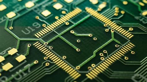
Printed Circuit Boards (PCBs) form the foundation of nearly all modern electronic devices. From smartphones to kitchen appliances, these flat boards with their distinctive copper traces provide the physical platform that connects electronic components in an organized, reliable manner. Simple PCB circuits offer an excellent starting point for electronics enthusiasts, students, and hobbyists to understand fundamental electronic principles while creating functional devices.
A PCB serves multiple purposes in electronic design:
- Provides mechanical support for components
- Creates electrical connections between components
- Offers protection against environmental factors
- Enables compact and organized circuit layouts
Simple PCB circuits typically contain basic components like resistors, capacitors, LEDs, transistors, and integrated circuits (ICs) arranged to perform specific functions. These beginner-friendly projects help build essential skills in circuit design, soldering, and troubleshooting.
Essential Components for Simple PCB Circuits
Before diving into circuit designs, it’s crucial to understand the basic components that appear in most simple PCB projects:
1. Resistors
These components limit current flow and divide voltages in circuits. Measured in ohms (Ω), resistors come with color-coded bands that indicate their resistance values. Common in voltage dividers, current limiting networks, and pull-up/pull-down configurations.
2. Capacitors
Capacitors store and release electrical energy. They come in various types:
- Ceramic capacitors (small values, non-polarized)
- Electrolytic capacitors (larger values, polarized)
- Tantalum capacitors (stable, polarized)
Used for filtering, timing circuits, and power supply stabilization.
3. Diodes
These semiconductor devices allow current to flow in one direction only. Special types include:
- Light Emitting Diodes (LEDs) – emit light when current passes through
- Zener diodes – maintain constant voltage
- Schottky diodes – fast switching applications
4. Transistors
The workhorses of modern electronics, transistors amplify or switch electronic signals. Common types:
- Bipolar Junction Transistors (BJTs) – NPN and PNP
- Field Effect Transistors (FETs) – including MOSFETs
5. Integrated Circuits (ICs)
These miniature circuits contain numerous components in a single package. Common simple ICs:
- 555 timer – for timing and oscillation
- 74 series logic chips – basic digital functions
- Voltage regulators (7805, LM317) – stable power supply
Fundamental Simple PCB Circuit Examples
1. LED Blinker Circuit
One of the simplest PCB projects, the LED blinker demonstrates basic timing and oscillation principles.
Components needed:
- 555 timer IC
- LED
- Resistors (1kΩ, 10kΩ)
- Capacitor (10μF)
- 9V power supply
How it works:
The 555 timer configured in astable mode creates a continuous square wave output. The timing components (resistor and capacitor) determine the blink rate. The LED connects to the output through a current-limiting resistor.
PCB considerations:
- Place timing components close to the 555 IC
- Include power supply decoupling capacitor near IC
- Provide clear polarity markings for LED
2. Voltage Regulator Circuit
A stable power supply is essential for most electronic projects.
Components needed:
- 7805 voltage regulator (5V output)
- Input and output capacitors (0.33μF and 0.1μF)
- Heat sink (for higher currents)
- Input power source (7-12V DC)
How it works:
The 7805 maintains a constant 5V output regardless of input voltage fluctuations (within specified limits). The capacitors filter noise and ensure stability.
PCB considerations:
- Provide adequate copper area for heat dissipation
- Include test points for input and output voltages
- Consider adding an LED power indicator
3. Light Sensor Circuit
This circuit demonstrates analog sensing using a Light Dependent Resistor (LDR).
Components needed:
- LDR
- Transistor (2N3904 or similar)
- Resistors (10kΩ, 1kΩ)
- LED (output indicator)
- 9V power supply
How it works:
The LDR’s resistance changes with light intensity, altering the transistor’s base current. This amplifies the change, making the LED brighter or dimmer according to ambient light.
PCB considerations:
- Position LDR where it can receive environmental light
- Include potentiometer for sensitivity adjustment
- Provide space for optional output connections
PCB Design Fundamentals for Simple Circuits
1. Schematic Capture
Before laying out a PCB, create a schematic diagram showing:
- All components with proper symbols
- Electrical connections (nets)
- Component values and designators
- Input/output points
Popular free schematic tools include:
- KiCad
- EasyEDA
- Fritzing (beginner-friendly)
2. Component Placement
Effective component arrangement:
- Group related components together
- Place connectors near board edges
- Consider heat-generating components
- Ensure adequate space for soldering
- Orient components in consistent directions when possible
3. Routing Considerations
When creating copper traces:
- Maintain appropriate trace widths for current (typically 10-20 mil for signals)
- Avoid sharp 90° angles (use 45° angles instead)
- Provide sufficient clearance between traces
- Consider ground planes for better performance
- Make power traces wider than signal traces
4. Design Rule Check (DRC)
Before manufacturing, run DRC to verify:
- Minimum spacing requirements
- Trace width compliance
- Hole sizes and annular rings
- Unconnected nets
- Other manufacturability factors
PCB Fabrication Options for Hobbyists
1. Etching at Home
Traditional method using:
- Copper-clad board
- Etchant solution (ferric chloride or ammonium persulfate)
- Toner transfer or photoresist method
Pros:
- Immediate results
- Low cost for simple boards
- Complete control over process
Cons:
- Messy chemicals
- Limited to simple designs
- No solder mask or silkscreen
2. CNC Milling
Using a small desktop CNC router to:
- Remove unwanted copper
- Drill holes
- Cut board outline
Pros:
- No chemicals needed
- Fast turnaround
- Can do double-sided boards
Cons:
- Limited resolution
- Requires expensive equipment
- Challenging for complex designs
3. Professional PCB Services
Online services like:
- JLCPCB
- PCBWay
- OSH Park
Pros:
- High-quality results
- Support complex designs
- Include solder mask and silkscreen
- Affordable for simple boards
Cons:
- Longer turnaround time
- Minimum order quantities
- Shipping costs
Soldering Techniques for Simple PCBs
1. Tools Required
- Temperature-controlled soldering iron (25-40W)
- Solder wire (lead-free or leaded, 0.8-1mm diameter)
- Soldering stand with sponge
- Tweezers and pliers
- Solder sucker or wick for desoldering
- Magnifying glass or microscope (optional)
2. Basic Soldering Steps
- Clean the PCB and component leads
- Insert component through holes
- Bend leads slightly to hold in place
- Heat both pad and lead simultaneously
- Apply solder to form concave fillet
- Remove solder then iron
- Inspect joint for proper formation
- Trim excess leads
3. Common Mistakes to Avoid
- Cold joints (insufficient heat)
- Bridging between pads
- Excessive solder
- Overheating components
- Poor pad-to-lead contact
Troubleshooting Simple PCB Circuits
Even well-designed circuits may require debugging:
1. Visual Inspection
- Check for incorrect component placement
- Look for solder bridges
- Verify proper polarity
- Examine for damaged components
2. Continuity Testing
Use a multimeter to:
- Verify power reaches all points
- Check for unintended shorts
- Test signal paths
3. Voltage Measurements
Compare measured voltages with expected values at:
- Power supply points
- IC pins
- Transistor terminals
4. Signal Tracing
For dynamic circuits:
- Use oscilloscope if available
- Check timing and waveforms
- Verify signal integrity
Expanding Simple PCB Skills
After mastering basic circuits, consider:
1. Surface Mount Technology (SMT)
- Smaller components
- Higher density layouts
- Requires different soldering techniques
2. Two-Layer Boards
- Routing on both sides
- Using vias for connections
- Improved signal routing
3. Mixed Signal Design
- Combining analog and digital circuits
- Managing noise and interference
- Proper grounding techniques
4. Microcontroller Integration
- Adding programmable elements
- Arduino-compatible designs
- Sensor interfacing
Conclusion
Simple PCB circuits provide an accessible entry point into the world of electronics design and fabrication. By starting with fundamental projects like LED blinkers, voltage regulators, and sensor circuits, beginners can develop essential skills in circuit theory, PCB layout, and soldering techniques. The satisfaction of designing, building, and troubleshooting a functional PCB creates a strong foundation for more complex electronic projects.
As skills progress, hobbyists can explore more advanced techniques including surface mount components, multilayer boards, and programmable circuits. The key to success lies in starting simple, thoroughly understanding each project, and gradually increasing complexity. With numerous affordable tools and resources available today, anyone with interest and patience can master the art of simple PCB circuits and unlock the potential to create custom electronic devices.
Remember that even the most sophisticated electronic systems are built upon the same basic principles demonstrated in these simple PCB circuits. By mastering these fundamentals, you establish the knowledge base needed to tackle increasingly challenging projects and potentially develop innovative electronic solutions of your own.


