Soldering Temperature for Circuit Boards: A Comprehensive Guide
Introduction
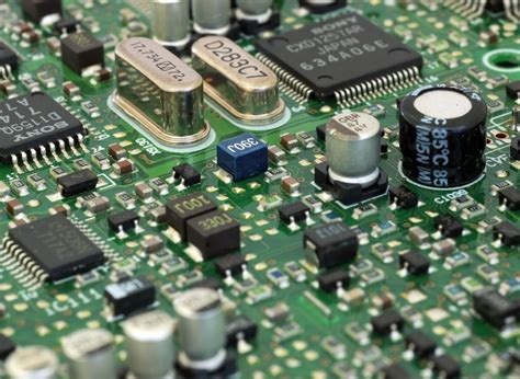
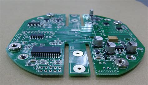
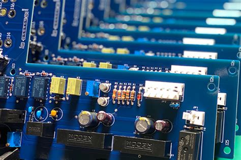
Soldering is a fundamental process in electronics manufacturing and repair, used to create strong electrical connections between components and printed circuit boards (PCBs). One of the most critical factors in achieving a reliable solder joint is temperature control. The soldering temperature affects the quality of the bond, the integrity of the components, and the overall performance of the circuit board.
This article explores the importance of soldering temperature, the optimal temperature ranges for different soldering techniques, factors influencing temperature selection, and best practices to ensure high-quality solder joints.
1. Importance of Soldering Temperature
Soldering temperature plays a crucial role in ensuring:
- Proper Wetting: The solder must melt and flow smoothly onto the metal surfaces (pads and leads) to form a strong bond.
- Component Safety: Excessive heat can damage sensitive electronic components, such as integrated circuits (ICs) or surface-mount devices (SMDs).
- Solder Joint Reliability: Too low a temperature results in cold joints (weak, brittle connections), while excessive heat can lead to oxidation or thermal stress.
- Flux Activation: The flux (a chemical cleaning agent) must reach its activation temperature to remove oxides and improve solder flow.
2. Optimal Soldering Temperature Ranges
The ideal soldering temperature depends on the type of solder alloy, soldering method, and components involved. Below are general guidelines for different soldering techniques:
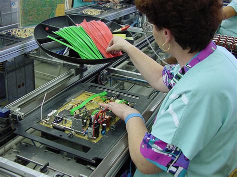
2.1 Hand Soldering with a Soldering Iron
- Recommended Temperature: 300°C to 380°C (572°F to 716°F)
- Factors to Consider:
- Lead-Based Solder (Sn-Pb, 63/37 or 60/40): Melts at around 183°C (361°F). A soldering iron tip temperature of 300°C–350°C is typically sufficient.
- Lead-Free Solder (SAC305, Sn-Ag-Cu): Melts at 217°C–227°C (422°F–440°F). Requires higher iron temperatures (350°C–380°C) due to poorer wetting properties.
- Component Sensitivity: Delicate components (e.g., LEDs, small SMDs) may need lower temperatures (280°C–320°C) to prevent damage.
2.2 Reflow Soldering (Oven-Based)
- Typical Temperature Profile:
- Preheat: Gradual ramp-up (~1–3°C/sec) to 150°C–200°C to avoid thermal shock.
- Soak (Flux Activation): 150°C–200°C for 60–120 seconds to allow flux to clean surfaces.
- Reflow (Peak Temperature): 220°C–250°C (lead-free: 240°C–260°C) for 30–60 seconds.
- Cooling: Controlled cooling (~1–4°C/sec) to solidify joints properly.
- Lead-Free Solder Considerations: Requires higher peak temperatures (~250°C) compared to leaded solder (~220°C).
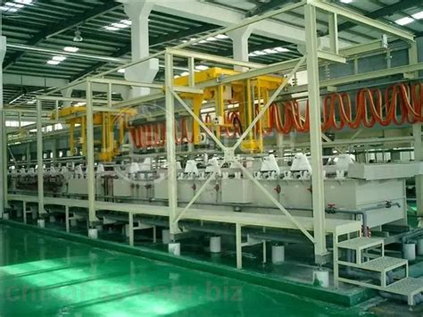
2.3 Wave Soldering (Through-Hole Components)
- Solder Bath Temperature: 250°C–270°C (lead-free: 260°C–280°C)
- Preheat Stage: 80°C–120°C to prevent thermal shock and activate flux.
- Contact Time: 2–5 seconds to ensure proper wetting without overheating components.
2.4 Desoldering (Removing Components)
- Temperature Range: 300°C–400°C, depending on solder alloy.
- Use of Desoldering Tools: Soldering irons, hot air guns, or desoldering pumps may require higher temps to melt aged or oxidized solder.
3. Factors Affecting Soldering Temperature Selection
Several variables influence the optimal soldering temperature:
3.1 Solder Alloy Composition
- Lead-Based Solder (Sn-Pb): Lower melting point (183°C) allows for lower soldering temperatures.
- Lead-Free Solder (SAC305, Sn-Cu, etc.): Higher melting point (217°C–227°C) requires increased temperatures.
- Low-Temperature Alloys (e.g., Sn-Bi): Used for heat-sensitive components, melting at ~138°C.
3.2 Component Thermal Sensitivity
- Through-Hole Components: Generally more heat-resistant.
- Surface-Mount Devices (SMDs): Smaller components (e.g., resistors, capacitors) can be damaged by excessive heat.
- Plastic Connectors & ICs: May warp or degrade above 250°C.
3.3 PCB Material & Thickness
- FR-4 (Standard PCB): Can withstand up to ~250°C–300°C before delamination.
- High-Tg (Glass Transition Temperature) PCBs: Better suited for lead-free soldering.
- Thick Boards: Require longer heating times but not necessarily higher temperatures.
3.4 Flux Type
- Rosin Flux: Activates at ~150°C–200°C.
- No-Clean Flux: Requires precise temperature control for proper activation.
- Water-Soluble Flux: More aggressive, works at slightly lower temps.
4. Consequences of Incorrect Soldering Temperature
4.1 Too Low Temperature
- Cold Joints: Dull, grainy, and weak connections prone to failure.
- Poor Wetting: Solder does not flow properly, leading to incomplete bonds.
- Increased Soldering Time: Prolonged heat exposure can still damage components.
4.2 Too High Temperature
- Thermal Damage: Components, PCB substrates, or copper traces may degrade.
- Oxidation: Excessive heat accelerates oxidation, reducing solderability.
- Flux Burn-Off: Flux evaporates too quickly, reducing its effectiveness.
- Lifted Pads: Overheating can cause copper pads to detach from the PCB.
5. Best Practices for Temperature Control
To achieve optimal soldering results:
- Use a Temperature-Controlled Soldering Iron: Adjustable irons prevent overheating.
- Follow Manufacturer Guidelines: Check datasheets for component and solder specifications.
- Preheat the PCB (For Reflow/Wave Soldering): Reduces thermal shock.
- Monitor Joint Quality: Shiny, smooth joints indicate proper temperature; dull joints suggest issues.
- Use Thermal Relief Pads: Helps dissipate heat in sensitive areas.
- Employ Thermocouples or IR Thermometers: Ensures accurate temperature monitoring.
6. Conclusion
Soldering temperature is a critical parameter that directly impacts the quality and reliability of circuit board assemblies. Whether using hand soldering, reflow, or wave soldering, selecting the correct temperature range ensures strong electrical connections while preventing damage to components and PCBs. By understanding the factors influencing temperature selection and adhering to best practices, technicians and engineers can achieve consistent, high-quality solder joints in their electronic projects.