Summary of software used in circuit development and design
What software do you need to learn for circuit development and design? Circuit design software refers to software for circuit diagram drawing, optimization, testing, and simulation. In China, the most developed and used circuit design software are as follows: protel, powerpcb, Allegro, orcad, cam350, etc. These circuit design software include functions such as electrical schematic drawing, printed circuit board design, digital circuit simulation, and programmable logic device design, which can help you develop and learn better. Below, the editor of Xianji.com will briefly introduce these software to you:
1.protel
protel is an EDA software launched by Altium in the late 1980s. Among the CAD software in the electronics industry, it deservedly ranks ahead of many EDA software and is the preferred software for electronic designers. It has been used in China for a long time and has the highest popularity in China. Some colleges and universities have also opened courses to learn it. Almost all electronic companies need to use it. Many large companies often write in their conditions when recruiting electronic design talents that they will use PROTEL.
Early PROTEL was mainly used as a printed circuit board automatic wiring tool, running in the DOS environment, and had very low hardware requirements. Today’s PROTEL has developed into DXP 2004, which is a huge EDA software with more than 200M fully installed. It works in the WINDOWS95 environment and is a complete board-level all-round electronic design system. It includes circuit schematic drawing, analog circuit and digital circuit mixed signal simulation, multi-layer printed circuit board design (including printed circuit board automatic wiring), programmable logic device design, chart generation, spreadsheet generation, support for macro operations and other functions, and has a Client/Server (client/server) architecture. It is also compatible with the file formats of some other design software, such as ORCAD, PSPICE, EXCEL, etc. Its automatic wiring of multi-layer printed circuit boards can achieve 100% routing rate of high-density PCBs.
In China, PROTEL software is relatively easy to buy, and there are many books about PROTEL software and instructions, which provides a basis for its popularization. If you want to learn more about PROTEL’s software functions or download a trial version of PROTEL99, you can go to the INTERNET.
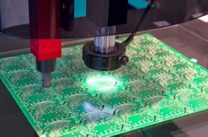
Circuit development and design software protel

2.powerpcb
powerpcb is a circuit design automation software promoted by Mentor Graphics in the United States. It is also one of the most widely used and best-performing EDA software in the field of electronic engineering.
Software for designing and making printed circuit board negatives. It is used in conjunction with Power Logic to support a variety of electronic components, such as resistors, capacitors, and multiple IC chips. PowerPCB is different from PSpice. The latter can simulate circuit characteristics, while the former cannot. The latest version is PADS9.5, which includes
Circuit simulation HyperLynx, high-speed PCB design PADS Route, schematic design DxDesigner, PADS Logic and simulation. PADS software is widely used in mobile phone PCB design, MID, and PCB design of other consumer electronic products. PADS software can directly import design drawings from other software, which is very convenient.
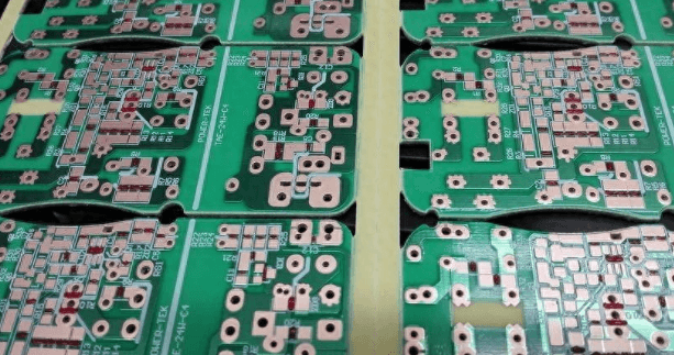
Circuit development and design software powerpcb
3.Allegro
Allegro is an advanced PCB design and wiring tool launched by Cadence. Allegro provides a good and interactive working interface and powerful and complete functions. The combination with its front-end products Cadence, OrCAD, and Capture provides the most perfect solution for the current high-speed, high-density, multi-layer complex PCB design and wiring. Allegro has a complete constraint setting. Users only need to set the wiring rules as required. The design requirements of the wiring can be met without violating the DRC during wiring, thus saving tedious manual inspection time and improving work efficiency! It can also define parameters such as minimum line width or line length to meet the various requirements of today’s high-speed circuit board wiring.
The ConstraintManger in the software provides a simple and clear interface for users to set and view constraint declarations. Its combination with Capture allows E.E. electronic engineers to set the rule data when drawing the circuit diagram, and can bring it to the Allegro working environment together, automatically processing and checking according to the rules when placing parts and wiring, and the experience values of these rule data can be reused in circuit board designs of the same nature.
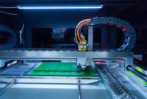
Circuit development and design software Allegro
4.Orcad
Orcad is a set of electronic design automation software for personal computers, which is specially used for electronic engineers to design circuit diagrams and related diagrams, design printed circuit boards, and simulate circuits.
Using Capture software, it is possible to draw circuit schematics and provide continuous simulation information for PCB production and programmable logic design. OrCAD Capture, as an industry-standard PCB schematic input method, is one of the most popular schematic input tools in the world today, with a simple and intuitive user design interface. OrCAD Capture CIS has a powerful component information system that can manage component databases online and centrally, thereby greatly improving the efficiency of circuit design. OrCAD Capture provides a complete and adjustable schematic design method that can be effectively applied to PCB design creation, management and reuse. Combining schematic design technology with PCB layout and routing technology, OrCAD can help designers grasp the design intent from the beginning. Whether it is used to design analog circuits, complex PCBs, FPGAs and CPLDs, schematic modification of PCB revisions, or for designing hierarchical modules, OrCAD Capture can provide designers with fast design input tools. In addition, OrCAD Capture schematic input technology allows designers to input, modify and verify PCB designs at any time.
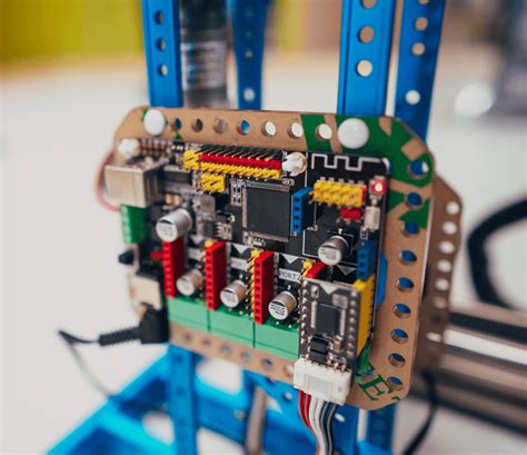
Circuit design and development software orcad
5.EWB
EWB is a very excellent circuit simulation software launched by Canadian Interactive Image Technologies Ltd in the early 1990s, which is specially used for the design and simulation of electronic circuits. EWB5.2 is currently widely used. Compared with other EDA software, it is a relatively small software (only 16M). However, its mixed simulation function for analog and digital circuits is very powerful, and it simulates the results of real circuits almost 100%. Compared with other circuit simulation software (such as Prote199se), it has the advantages of intuitive interface, convenient operation, easy to learn and use. EWB provides multimeters, oscilloscopes, signal generators, sweep meters, logic analyzers, digital signal generators, logic converters, voltmeters, ammeters and other instruments on the desktop. The components and test instruments for creating circuits can be directly selected from the device library and instrument library on the screen. The analysis, design and simulation of electronic circuits are contained in the click of the mouse, which not only brings endless fun to electronic circuit designers, but also greatly improves the quality and efficiency of electronic design work.