Techniques for Improving PCB Reliability
Introduction
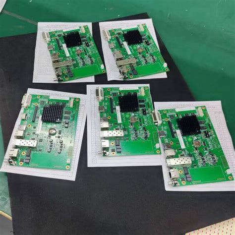
Printed Circuit Boards (PCBs) are the backbone of modern electronics, serving as the foundation for nearly all electronic devices, from smartphones to industrial machinery. As electronic systems become more complex, the reliability of PCBs becomes increasingly critical. A failure in a PCB can lead to system malfunctions, costly repairs, or even safety hazards. Therefore, improving PCB reliability is essential for ensuring long-term performance and reducing failure rates.
This article explores various techniques for enhancing PCB reliability, covering design considerations, material selection, manufacturing processes, testing methods, and environmental protection strategies.
1. Design Considerations for PCB Reliability
1.1 Proper Layout and Routing
A well-designed PCB layout minimizes signal interference, thermal stress, and mechanical strain. Key practices include:
- Signal Integrity: Proper trace spacing and impedance control reduce crosstalk and electromagnetic interference (EMI).
- Thermal Management: Adequate copper pours, thermal vias, and heat sinks prevent overheating.
- Mechanical Stability: Avoiding sharp angles in traces reduces stress concentrations.
1.2 Component Placement
Strategic component placement improves reliability by:
- Minimizing Signal Path Lengths: Reducing trace lengths lowers resistance and inductance.
- Balancing Thermal Loads: Distributing heat-generating components prevents localized overheating.
- Ensuring Accessibility: Proper spacing facilitates assembly, testing, and repairs.
1.3 Use of Design for Manufacturing (DFM) and Design for Reliability (DFR)
DFM and DFR principles ensure that PCBs are manufacturable and robust:
- DFM Guidelines: Follow manufacturer-recommended tolerances for trace widths, hole sizes, and clearances.
- DFR Techniques: Incorporate redundancy, derating, and failure mode analysis in design.
2. Material Selection for Enhanced Reliability
2.1 High-Quality Substrate Materials
The choice of PCB substrate significantly impacts reliability:
- FR-4: Standard material with good mechanical and electrical properties.
- High-Tg (Glass Transition Temperature) Materials: Suitable for high-temperature applications.
- Flexible Substrates (Polyimide): Used in flexible PCBs for dynamic applications.
2.2 Copper Foil Quality
High-quality copper with proper thickness ensures:
- Better Conductivity: Reduces resistive losses.
- Improved Adhesion: Prevents delamination under thermal cycling.
2.3 Solder Mask and Surface Finish
- Solder Mask: Protects against oxidation and short circuits.
- Surface Finishes (ENIG, HASL, OSP): Enhance solderability and corrosion resistance.
3. Manufacturing Process Optimization
3.1 Controlled Fabrication Processes
- Precision Etching: Ensures accurate trace dimensions.
- Lamination Quality: Prevents voids and delamination.
- Drilling Accuracy: Minimizes misalignment and via defects.
3.2 Soldering Techniques
- Reflow Soldering: Ensures consistent solder joints.
- Wave Soldering: Suitable for through-hole components.
- Selective Soldering: Reduces thermal stress on sensitive components.
3.3 Inspection and Quality Control
- Automated Optical Inspection (AOI): Detects soldering defects.
- X-Ray Inspection: Identifies hidden defects in BGAs and vias.
- Electrical Testing: Verifies connectivity and functionality.
4. Testing and Validation Methods
4.1 Environmental Stress Testing
- Thermal Cycling: Evaluates performance under temperature variations.
- Humidity Testing: Assesses resistance to moisture.
- Vibration and Shock Testing: Ensures mechanical durability.
4.2 Accelerated Life Testing
Simulates long-term usage in a shorter time to predict failure modes.
4.3 Signal Integrity Testing
- Time-Domain Reflectometry (TDR): Identifies impedance mismatches.
- Eye Diagram Analysis: Evaluates high-speed signal quality.
5. Protection Against Environmental Factors
5.1 Conformal Coating
Protects PCBs from moisture, dust, and chemicals. Common coatings include:
- Acrylic: Easy to apply and repair.
- Silicone: Flexible and heat-resistant.
- Polyurethane: Highly durable.
5.2 Encapsulation
Potting compounds provide additional mechanical and environmental protection.
5.3 Corrosion Prevention
- Use of Anti-Corrosive Materials: Such as gold or silver plating.
- Hermetic Sealing: For extreme environments.
6. Maintenance and Failure Analysis
6.1 Regular Inspection
Periodic checks for signs of wear, corrosion, or thermal damage.
6.2 Root Cause Analysis (RCA)
Investigating failures to prevent recurrence. Techniques include:
- Microscopic Examination: Identifies cracks or solder defects.
- Thermal Imaging: Detects hotspots.
6.3 Repair and Rework Techniques
- Desoldering and Resoldering: For component replacement.
- Trace Repair: Using conductive epoxy or jumper wires.
Conclusion
Improving PCB reliability requires a holistic approach, encompassing design, material selection, manufacturing, testing, and environmental protection. By implementing these techniques, manufacturers can produce robust PCBs that withstand harsh conditions, reduce failure rates, and extend product lifespans. As technology advances, continuous innovation in PCB reliability will remain crucial for the future of electronics.
Key Takeaways:
- Design wisely to minimize stress and signal issues.
- Choose high-quality materials for durability.
- Optimize manufacturing to avoid defects.
- Test rigorously to ensure performance.
- Protect against environmental factors to enhance longevity.
By following these best practices, engineers and manufacturers can achieve highly reliable PCBs that meet the demands of modern electronic applications
This article provides a comprehensive overview of PCB reliability techniques. Let me know if you’d like any modifications or additional details!


