Terminal Block PCB: Design, Types, and Applications
Introduction to Terminal Block PCBs
Terminal block printed circuit boards (PCBs) represent a critical component in modern electrical and electronic systems, providing secure and reliable connection points between circuits and external wiring. These specialized PCBs incorporate terminal blocks – modular, insulated devices that facilitate the connection of multiple wires without splicing or direct soldering to the circuit board itself.
The integration of terminal blocks onto PCBs has revolutionized electrical interconnection technology by offering:
- Simplified wiring processes
- Enhanced maintenance capabilities
- Improved system organization
- Increased safety through proper insulation
- Standardized connection points
This comprehensive article explores terminal block PCB technology, examining design considerations, various types available, manufacturing processes, and their wide-ranging applications across industries.
Fundamentals of Terminal Block PCB Design
Basic Structure and Components
A terminal block PCB consists of three primary elements:
- The PCB substrate: Typically made from FR-4 material, providing the foundation for both the terminal blocks and associated circuitry.
- Terminal blocks: Modular components mounted to the PCB that contain:
- Conductors (usually copper alloys)
- Screw or spring clamping mechanisms
- Insulating housing (often thermoplastic)
- Interconnection circuitry: Copper traces that connect the terminal blocks to other components on the PCB.
Key Design Parameters
When designing terminal block PCBs, engineers must consider several critical parameters:
Electrical Considerations:
- Current rating (typically 5A to 100A)
- Voltage rating (commonly 150V to 600V)
- Contact resistance (usually <5mΩ)
- Dielectric strength (often 2-4kV)
- Pitch (standard spacing between connections: 3.5mm, 5mm, 7.5mm, 10mm)
Mechanical Considerations:
- Wire size compatibility (AWG ranges)
- Clamping force (typically 0.5-1.5 Nm torque)
- Vibration resistance
- IP rating for environmental protection
Thermal Considerations:
- Temperature rating of materials (-40°C to +125°C common)
- Heat dissipation requirements
- Thermal expansion coefficients
PCB Layout Guidelines
Proper layout is essential for optimal performance:
- Placement: Position terminal blocks along board edges for easy access, considering wire bending radius requirements.
- Clearances: Maintain adequate creepage and clearance distances according to IEC 60664 standards:
- 0.8mm for 50V
- 1.5mm for 150V
- 3.0mm for 300V
- Trace Sizing: Calculate trace widths based on current carrying requirements using IPC-2221 formulas or online calculators.
- Mounting: Include appropriate mounting holes or panel attachments for secure installation.
- Labeling: Implement clear, durable markings for terminal identification.
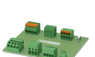
Types of Terminal Blocks for PCB Mounting
Classification by Connection Technology
1. Screw Terminal Blocks
- Most common type
- Secure wires with screw-driven clamping plates
- Advantages: High reliability, good for large wires
- Disadvantages: May loosen under vibration
2. Spring-Clamp Terminal Blocks
- Use spring pressure to maintain connection
- Advantages: Faster installation, vibration-resistant
- Disadvantages: Limited to smaller wire gauges
3. Push-In Terminal Blocks
- Allow wire insertion without tools
- Advantages: Extremely quick installation
- Disadvantages: Specialized wire preparation often needed
4. Barrier Terminal Blocks
- Feature separated connection points
- Advantages: Prevents accidental shorts
- Disadvantages: Larger footprint
5. Pluggable Terminal Blocks
- Allow modular disconnection
- Advantages: Easy maintenance
- Disadvantages: Additional cost
Specialized Terminal Block Varieties
High-Current Terminal Blocks
- Designed for 20A+ applications
- Features: Larger contacts, heat dissipation
High-Voltage Terminal Blocks
- Rated for 1kV+ applications
- Features: Extended creepage distances
Sensor/Actuator Terminal Blocks
- Designed for industrial I/O
- Features: Spring clamps, marking fields
Fused Terminal Blocks
- Incorporate fuse protection
- Features: Replaceable fuse elements
Ground Terminal Blocks
- Specifically for grounding applications
- Features: Distinctive color (often green/yellow)

Terminal Block PCB Manufacturing Processes
Material Selection
PCB Substrate:
- Standard: FR-4 (flame retardant epoxy)
- High-temperature: Polyimide or ceramic-filled
- Flexible: Polyimide films
Terminal Block Materials:
- Housing: Thermoplastics (PA, PBT, PC)
- Contacts: Copper alloys (often tin or gold plated)
- Clamping: Steel or brass components
Manufacturing Steps
- PCB Fabrication
- Standard multilayer PCB production
- Special attention to pad sizes for terminal blocks
- Terminal Block Production
- Injection molding of housing
- Metal stamping for contacts
- Assembly of clamping mechanisms
- Assembly Process
- SMT or through-hole mounting
- Wave soldering for through-hole types
- Potential for automated assembly
- Quality Testing
- Continuity testing
- Insulation resistance verification
- Mechanical strength testing
Advanced Manufacturing Techniques
Automated Optical Inspection (AOI):
- Verifies proper terminal block placement
- Checks solder joint quality
In-Circuit Testing (ICT):
- Tests electrical characteristics
- Verifies proper connections
Environmental Stress Screening:
- Thermal cycling
- Vibration testing
Applications of Terminal Block PCBs
Industrial Automation
Terminal block PCBs are ubiquitous in industrial control systems:
- PLC (Programmable Logic Controller) interfaces
- Motor control centers
- Sensor and actuator connections
- Power distribution panels
Advantages in industrial settings:
- Simplified maintenance
- Reduced downtime during repairs
- Standardized wiring
Power Electronics
Critical applications include:
- Power supplies
- Inverters and converters
- Renewable energy systems (solar, wind)
- UPS (Uninterruptible Power Supply) systems
Design considerations:
- High-current handling
- Thermal management
- Safety isolation
Building Automation
Widespread use in:
- HVAC control systems
- Lighting control panels
- Security system interfaces
- Elevator control systems
Benefits for building systems:
- Easy field modifications
- Clear wiring identification
- Reliable long-term connections
Transportation Systems
Applications in:
- Automotive electronics (especially electric vehicles)
- Railway signaling and control
- Aerospace avionics
- Marine electrical systems
Special requirements:
- Vibration resistance
- Harsh environment tolerance
- Lightweight designs
Consumer Electronics
Found in:
- Home appliances
- Audio/video equipment
- Computer peripherals
- Smart home devices
Design trends:
- Miniaturization
- Push-in connection technology
- Aesthetic integration
Emerging Trends and Future Developments
Miniaturization
Ongoing developments include:
- Micro-terminal blocks with 2.5mm pitch
- Low-profile designs for space-constrained applications
- High-density arrangements
Smart Terminal Blocks
Innovative features emerging:
- Integrated current sensing
- Temperature monitoring
- Connection status detection
- RFID tagging for maintenance tracking
Advanced Materials
Material science advancements:
- Higher temperature thermoplastics
- Improved contact plating for reliability
- Environmentally friendly materials
Automation Compatibility
Designs optimized for:
- Robotic wire insertion
- Automated testing
- Industry 4.0 integration
Sustainable Designs
Eco-friendly developments:
- Lead-free materials
- Halogen-free housings
- Recyclable components
Conclusion
Terminal block PCBs represent a mature yet continually evolving technology that bridges the gap between circuit board electronics and the physical wiring of electrical systems. Their design sophistication has grown from simple screw terminals to advanced, application-specific solutions that address the needs of modern electrical and electronic systems across industries.
The versatility of terminal block PCBs – offering everything from basic wire connection points to smart, monitored interfaces – ensures their continued relevance in an increasingly connected and electrified world. As technologies advance, we can expect to see further integration of intelligent features, enhanced materials, and designs that push the boundaries of miniaturization while maintaining or improving performance characteristics.
For engineers and designers, understanding terminal block PCB technology is essential for creating reliable, maintainable, and efficient electrical systems. Proper selection and implementation can significantly impact product performance, safety, and total cost of ownership across the system lifecycle.