The Impact of Surface Mount Components on PCB Support Stands
Abstract
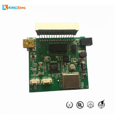
The increasing miniaturization and complexity of electronic devices have led to the widespread adoption of surface mount technology (SMT) in printed circuit board (PCB) manufacturing. While SMT components offer advantages such as reduced size, improved performance, and higher assembly density, their influence on PCB support structures—particularly support stands (also known as PCB spacers or standoffs)—has not been extensively studied. This paper examines how surface mount components affect PCB support stands in terms of mechanical stability, thermal management, vibration resistance, and assembly considerations. The findings suggest that while SMT components can enhance PCB design flexibility, they also introduce challenges that must be addressed to ensure structural integrity and long-term reliability.
1. Introduction
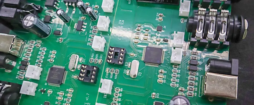
Printed circuit boards (PCBs) are fundamental to modern electronics, providing mechanical support and electrical connections for components. PCB support stands are critical in securing PCBs within enclosures, preventing excessive flexing, and maintaining proper alignment. With the shift from through-hole technology (THT) to surface mount technology (SMT), the mechanical and thermal dynamics of PCBs have evolved.
Surface mount components, unlike their through-hole counterparts, are mounted directly onto the PCB surface, eliminating the need for drilled holes. This change affects how forces are distributed across the board, influencing the performance of support stands. This paper explores the key factors that determine how SMT components interact with PCB support structures and provides recommendations for optimizing PCB design.
2. Mechanical Stability and Load Distribution
2.1 Weight Distribution
Traditional through-hole components contribute to PCB rigidity due to their insertion into plated holes, which reinforces the board structure. In contrast, SMT components rely solely on solder joints for attachment, which may lead to uneven stress distribution.
- Lightweight Nature of SMT Components: Most SMT components are smaller and lighter than through-hole parts, reducing the overall PCB weight. This can lessen the load on support stands, potentially allowing for fewer or smaller stands.
- Concentrated Mass Areas: High-density SMT layouts, such as those with ball grid array (BGA) packages, can create localized stress points. If not properly supported, these areas may induce bending or warping, leading to solder joint fatigue.
2.2 Flexural Rigidity
PCBs with SMT components are generally more susceptible to flexing due to the absence of through-hole anchoring. Support stands must be strategically placed to counteract this:
- Increased Stand Density Near Heavy Components: Areas with large SMT components (e.g., power inductors or connectors) may require additional support to prevent mechanical failure.
- Impact of Board Thickness: Thinner PCBs, often used in SMT designs for space savings, are more prone to flexing. Support stands must compensate for reduced inherent stiffness.
3. Thermal Management Considerations
3.1 Heat Dissipation and Expansion
SMT components generate heat during operation, which can affect both the PCB and support stands:
- Thermal Expansion Mismatch: Different coefficients of thermal expansion (CTE) between the PCB, components, and support stands can induce stress. Metal standoffs, for example, expand differently from FR4 substrates, potentially warping the board.
- Heat Transfer Pathways: Some support stands are designed to aid in heat dissipation. However, SMT components with thermal pads or heatsinks may alter heat flow, requiring thermal analysis to optimize stand placement.
3.2 Reflow Soldering Effects
During reflow soldering, SMT PCBs undergo significant thermal cycling, which can affect support stand integrity:
- Solder Reflow Temperatures: High temperatures may soften plastic support stands or weaken adhesive-based mounts.
- Post-Assembly Warpage: Uneven cooling after reflow can cause PCB warping, altering the load on support stands and potentially misaligning the board within its enclosure.
4. Vibration and Shock Resistance
4.1 Solder Joint Reliability
SMT components are more vulnerable to vibration-induced failures than through-hole parts due to their reliance on surface solder joints. Support stands play a crucial role in mitigating vibration effects:
- Damping Vibrations: Properly spaced support stands can reduce resonant frequencies that might otherwise fatigue solder joints.
- Stiffening the Assembly: In high-vibration environments (e.g., automotive or aerospace applications), additional supports may be necessary to prevent component detachment.
4.2 Impact of Component Density
Higher SMT component density increases the risk of mechanical interference during shock events:
- Stand Height Considerations: Taller components near support stands may require modified standoff heights to avoid contact during deflection.
- Board Stiffening Techniques: Stiffeners or reinforced support stands may be needed in areas with fragile components (e.g., ceramic capacitors).

5. Assembly and Manufacturing Factors
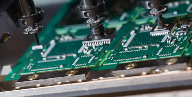
5.1 Automated Handling and Support Stand Placement
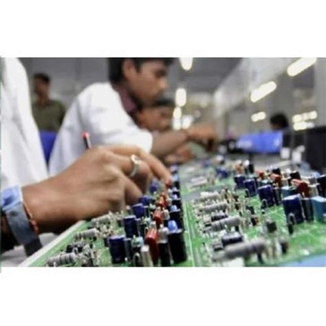
SMT assembly lines use pick-and-place machines and reflow ovens, which impose constraints on support stand design:
- Interference with Placement Nozzles: Support stands must not obstruct robotic assembly processes.
- Pre- vs. Post-Assembly Mounting: Some stands are installed before SMT reflow, while others are added afterward. Material selection must account for thermal exposure.
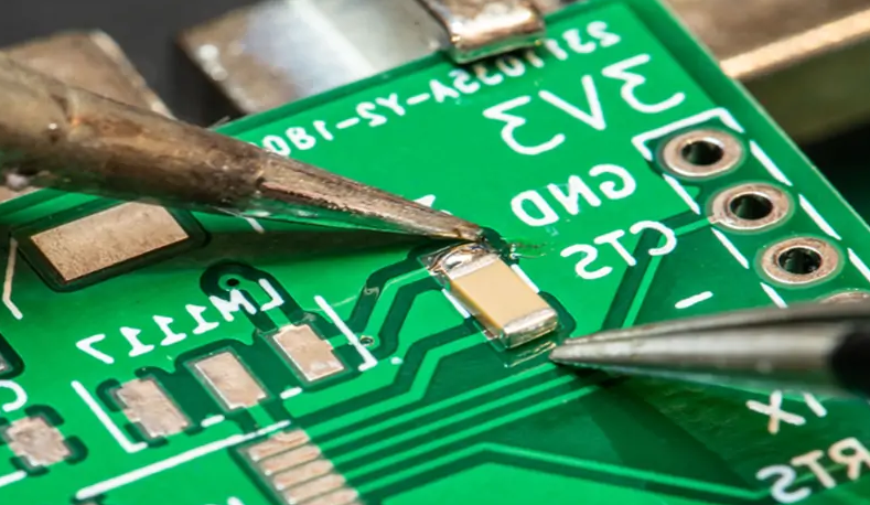
5.2 Rework and Repair Challenges
SMT rework (e.g., replacing BGA chips) can be complicated by support stand placement:
- Accessibility for Hot Air Rework: Stands should not block access to critical components.
- Mechanical Stress During Rework: Removing and replacing components near support stands may require temporary stand removal to avoid PCB damage.
6. Design Recommendations
To mitigate the challenges posed by SMT components on PCB support stands, designers should consider the following:
- Finite Element Analysis (FEA): Simulate mechanical and thermal stresses to optimize stand placement.
- Material Selection: Use support stands with CTE values compatible with the PCB substrate.
- Thermal Relief Strategies: Incorporate thermally conductive stands or additional cooling paths for high-power SMT components.
- Vibration Testing: Validate support stand configurations under real-world vibration conditions.
- Modular Support Designs: Use adjustable or removable stands to facilitate rework.
7. Conclusion
Surface mount technology has revolutionized PCB design, but its impact on support structures cannot be overlooked. While SMT components reduce weight and enable higher circuit density, they introduce new challenges in mechanical stability, thermal management, and vibration resistance. By carefully analyzing load distribution, thermal expansion effects, and assembly requirements, engineers can optimize support stand configurations to ensure PCB reliability. Future advancements in support stand materials and adaptive mounting systems may further enhance compatibility with evolving SMT trends
.