The Importance of Threads in PCB Circuit Boards
Abstract
This paper explores the critical role of threaded features in printed circuit board (PCB) design and manufacturing. While often overlooked, threaded elements in PCBs serve essential functions in mechanical assembly, thermal management, structural integrity, and long-term reliability. The article examines various types of PCB threading applications, their manufacturing processes, design considerations, and the consequences of improper thread implementation. Through analysis of current industry practices and emerging technologies, this work demonstrates how proper thread design contributes significantly to the overall performance and durability of electronic assemblies.
1. Introduction
Printed circuit boards form the foundation of modern electronics, providing both electrical connectivity and mechanical support for components. Among the myriad design elements in PCBs, threaded features—though physically small—play a disproportionately important role in ensuring proper function and reliability. Threads in PCBs typically appear as:
- Mounting holes for chassis or heat sink attachment
- Standoff connections for board stacking
- Component retention mechanisms
- Serviceable connection points
The increasing miniaturization and power density of electronic devices has made proper thread design more crucial than ever. This paper systematically examines why these small mechanical features deserve significant attention in PCB design processes.
2. Mechanical Assembly Considerations
2.1 Board Mounting and Alignment
Threaded mounting holes serve as the primary interface between PCBs and their enclosures or mechanical supports. Properly designed threads:
- Maintain precise board positioning during operation
- Prevent movement-induced stress on solder joints
- Allow for consistent alignment in multi-board systems
- Facilitate proper connector mating in modular designs
Industry studies show that approximately 23% of field failures in industrial electronics originate from mechanical mounting issues, many related to inadequate threaded connections.
2.2 Vibration and Shock Resistance
Electronic devices frequently encounter mechanical stresses during:
- Transportation and handling
- Operation in mobile environments (vehicles, aircraft)
- Industrial vibration exposure
Threaded fasteners, when properly specified, provide superior resistance to vibrational loosening compared to press-fit or adhesive alternatives. The helical structure of threads creates continuous friction surfaces that resist reverse rotation under dynamic loads.
3. Thermal Management Applications
3.1 Heat Sink Attachment
Modern high-power electronics generate substantial thermal loads requiring efficient heat dissipation. Threaded mounting provides:
- Consistent pressure for optimal thermal interface contact
- Removability for maintenance and TIM reapplication
- Mechanical stability under thermal cycling conditions
Research indicates that improper heat sink mounting pressure (often due to thread stripping or insufficient engagement) can increase junction temperatures by 15-20°C, significantly reducing component lifespan.
3.2 Thermal Expansion Accommodation
Different materials in electronic assemblies exhibit varying coefficients of thermal expansion (CTE). Threaded connections:
- Allow for controlled movement during temperature changes
- Maintain electrical connections while accommodating mechanical stress
- Prevent warping-induced failures in large PCBs
4. Structural Integrity Factors
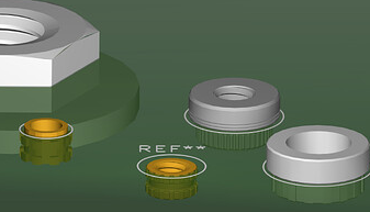
4.1 Plated Through-Hole vs. Non-Plated Threads
PCB threads generally fall into two manufacturing categories:
Plated through-hole threads:
- Created by tapping after copper plating process
- Provide electrical connectivity through the board
- Offer superior mechanical strength
- More expensive to produce
Non-plated threads:
- Machined directly into substrate material
- Lower cost implementation
- Limited reuse capability
- No electrical connectivity
4.2 Material Considerations
Thread strength depends heavily on PCB substrate materials:
- FR-4: Standard material, requires careful thread design
- Metal-core boards: Allow for robust threading
- High-Tg materials: Improved thermal performance
- Ceramic substrates: Special threading techniques required
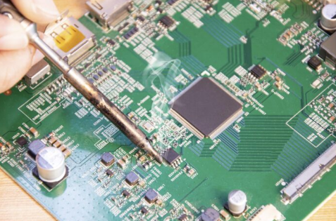
5. Manufacturing Processes
5.1 Thread Formation Methods
Common PCB threading techniques include:
Mechanical tapping:
- Traditional method using cutting taps
- Suitable for prototype and low-volume production
- Risk of material chipping in brittle substrates
Molded threads:
- Formed during PCB laminate pressing
- Excellent consistency in high-volume production
- Limited to certain substrate materials
Threaded inserts:
- Press-fit or thermally installed metal elements
- Provides most durable threading solution
- Additional cost and assembly steps
5.2 Quality Control Measures
Critical thread inspection parameters:
- Thread pitch diameter verification
- Engagement depth consistency
- Surface finish evaluation
- Plating thickness measurement (for plated threads)
Automated optical inspection (AOI) systems now incorporate thread measurement capabilities with micron-level precision.
6. Design Guidelines
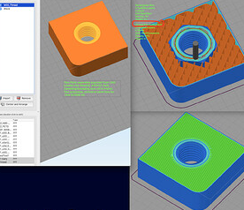
6.1 Hole Size and Thread Selection
Proper design requires consideration of:
- Material thickness and strength
- Expected mechanical loads
- Environmental conditions
- Assembly/disassembly frequency
Standard thread sizes for PCBs typically range from M2 to M6, with finer pitches preferred for thin substrates.
6.2 Keepout Areas and Clearances
Critical design rules include:
- Minimum edge clearance (typically 1.5× hole diameter)
- Component keepout zones around mounting points
- Copper pour clearance for non-plated threads
- Via protection near threaded areas
6.3 CAD Implementation
Modern PCB design software includes specialized tools for:
- Thread modeling and visualization
- DFM (design for manufacturability) checks
- Assembly interference detection
- Thermal expansion simulation
7. Reliability and Maintenance
7.1 Thread Degradation Mechanisms
Common failure modes include:
- Stripping from over-torque
- Fatigue cracking from cyclic loads
- Corrosion in harsh environments
- Galling during repeated assembly
7.2 Repair and Rework Options
Damaged thread solutions:
- Helicoil or threaded insert installation
- Oversize tapping with matching fastener
- Epoxy reinforcement for non-critical applications
8. Emerging Technologies
8.1 Advanced Materials
Innovations impacting PCB threading:
- Nanocomposite substrates with enhanced strength
- Self-healing polymers for thread repair
- Conductive adhesives combining electrical and mechanical functions
8.2 Additive Manufacturing
3D printing enables:
- Complex internal thread geometries
- Graded material properties
- Integrated thread and circuit formation
9. Conclusion
Threaded features in PCB designs represent a critical intersection of mechanical and electrical engineering requirements. Proper thread implementation ensures reliable operation across the product lifecycle while enabling necessary maintenance and serviceability. As electronic devices continue evolving toward higher densities and more demanding operating environments, attention to these small but vital features will grow increasingly important. Design engineers must consider threading requirements early in the development process and maintain awareness of both traditional best practices and emerging technological solutions.
Future developments in materials science and manufacturing technologies promise to expand PCB threading capabilities, enabling more robust and reliable electronic systems across all industries. The humble thread, often overlooked in the complexity of modern circuit design, remains an essential element in electronic product realization.