The Printed Circuit Board (PCB) in Touch-Controlled Lamps: Design and Functionality
Introduction
The touch-controlled lamp has become a ubiquitous feature in modern homes and offices, offering users a convenient and elegant way to control lighting. At the heart of these sophisticated devices lies the printed circuit board (PCB), which serves as the central nervous system of the lamp’s operation. This article explores the design, components, and functionality of PCBs used in touch-controlled lamps, examining how they translate human touch into electrical signals that control illumination.
Fundamental Principles of Touch Control Technology
Touch-controlled lamps utilize capacitive sensing technology to detect user input. When a human finger touches the designated area of the lamp, it alters the capacitance of the sensing circuit on the PCB. This change is detected by specialized ICs (integrated circuits) which then process the signal and trigger the appropriate response – typically toggling the light on/off or adjusting brightness levels.
There are two primary types of touch sensing used in lamps:
- Capacitive touch sensing: Measures changes in capacitance when a conductive object (like a finger) approaches or touches the sensor
- Resistive touch sensing: Detects actual pressure on the surface (less common in modern touch lamps)
The PCB integrates these sensing technologies with power regulation and lighting control circuits to create a complete system.
PCB Layout and Key Components
The PCB in a touch-controlled lamp typically features several critical components arranged in a specific layout to optimize performance and minimize interference:
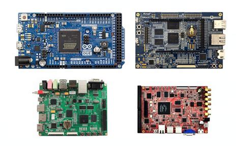
1. Microcontroller Unit (MCU)
The brain of the operation, usually an 8-bit or 32-bit microcontroller that:
- Processes touch input signals
- Controls lamp output states
- Manages brightness levels
- Handles timing functions (for features like automatic shut-off)
2. Capacitive Touch Sensor IC
Specialized chips like the AT42QT1010 or TTP223 handle touch detection by:
- Continuously monitoring capacitance changes
- Filtering out environmental noise
- Providing clean digital output to the MCU
3. Power Regulation Circuit
Converts incoming AC power (for plug-in lamps) or manages battery power (for portable models) through:
- Voltage regulators (e.g., 7805 for 5V systems)
- Rectifiers for AC/DC conversion
- Filter capacitors to smooth power delivery
4. Triac or MOSFET Switching Circuit
Controls the actual lamp output using:
- Triacs for AC lamp control (common in plug-in models)
- MOSFETs for DC control (common in battery-powered or LED lamps)
5. LED Driver Circuit (for LED models)
In LED-based touch lamps, this might include:
- Constant current drivers
- PWM controllers for dimming
- Voltage boost/buck converters as needed
6. Feedback Components
Some designs incorporate:
- Status LEDs
- Audible feedback buzzers
- Haptic feedback components
PCB Design Considerations
Designing a PCB for touch-controlled lamps requires careful attention to several factors:
1. Sensor Placement and Routing
The touch sensor pads or traces must be:
- Positioned close to the intended touch area
- Routed carefully to avoid noise pickup
- Properly shielded when necessary
- Sized appropriately for reliable detection
2. Power Supply Design
Must account for:
- Clean power delivery to sensitive analog touch circuits
- Proper grounding schemes
- Adequate filtering to prevent false triggering
3. Signal Integrity
Important considerations include:
- Minimizing parallel high-speed traces near sensitive analog circuits
- Proper trace widths for current-carrying capacity
- Careful layout to prevent capacitive coupling between unrelated circuits
4. EMI/EMC Considerations
The design must:
- Meet regulatory requirements for electromagnetic emissions
- Incorporate proper shielding if needed
- Include necessary filtering components
5. Manufacturing Constraints
Designers must consider:
- PCB material selection (typically FR-4)
- Layer count (often 2-layer for cost-sensitive designs)
- Assembly processes (through-hole vs. SMD components)
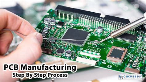
Manufacturing Process
The production of touch lamp PCBs follows standard PCB fabrication processes with some special considerations:
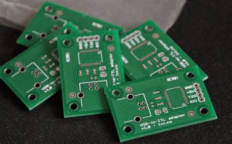
- Substrate Preparation: FR-4 material is most common
- Copper Patterning: Using etching or additive processes
- Touch Sensor Creation: Special attention to sensor pad finish (often HASL or ENIG)
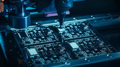
- Component Placement: Automated pick-and-place for SMD components
- Soldering: Reflow for SMD, wave or hand soldering for through-hole
- Testing: Specialized testing for touch sensitivity and response
- Conformal Coating: Optional for protection in humid environments
Advanced Features in Modern Touch Lamp PCBs
Contemporary touch-controlled lamp PCBs often incorporate additional sophisticated features:
1. Multi-Level Touch Control
Advanced designs can distinguish between:
- Short taps (on/off)
- Long presses (brightness adjustment)
- Multiple touches (special modes)
2. Wireless Connectivity
Some high-end models include:
- Bluetooth for smartphone control
- WiFi for IoT integration
- RF for remote control compatibility
3. Ambient Light Sensing
Automatic brightness adjustment based on:
- Room light levels
- Time of day
- User preferences
4. Energy Monitoring
Features that track and report:
- Power consumption
- Usage patterns
- Energy savings
5. Memory Functions
Storing user preferences for:
- Favorite brightness levels
- Automatic shut-off timing
- Custom color temperatures (for RGB models)
Troubleshooting Common PCB Issues
Common problems with touch lamp PCBs and their potential solutions:
- Inconsistent Touch Response:
- Check sensor pad connections
- Verify proper grounding
- Examine power supply stability
- False Triggering:
- Review filtering capacitor values
- Check for environmental EMI sources
- Verify proper sensor sensitivity settings
- No Power:
- Test voltage regulators
- Check fuse or polyfuse
- Verify AC/DC conversion components
- LED Flickering:
- Examine driver circuit
- Check for cold solder joints
- Verify PWM signal integrity
Future Trends in Touch Lamp PCB Design
Emerging technologies influencing touch lamp PCB development:
- Flexible PCBs: Enabling innovative lamp form factors
- Transparent Conductive Materials: For invisible touch interfaces
- Advanced Gesture Control: Beyond simple touch detection
- Energy Harvesting: Incorporating solar or kinetic energy recovery
- AI Integration: Adaptive learning of user preferences
Conclusion
The printed circuit board is the unsung hero of touch-controlled lamps, transforming a simple lighting fixture into an intelligent, interactive device. From basic capacitive sensing to advanced wireless-connected systems, the PCB’s design and implementation determine the lamp’s functionality, reliability, and user experience. As technology continues to advance, we can expect touch lamp PCBs to incorporate even more sophisticated features while becoming smaller, more efficient, and more cost-effective. Understanding the principles behind these PCBs not only helps in troubleshooting and repair but also provides insight into the remarkable engineering that goes into these seemingly simple everyday devices.
The continued evolution of touch lamp PCBs will likely follow broader trends in electronics – greater integration, improved energy efficiency, enhanced connectivity, and more intuitive user interfaces. For engineers and hobbyists alike, these devices represent an accessible yet technologically rich area for exploration and innovation in the field of consumer electronics.