The Relationship Between ESR and ESL of Thermal Loop PCBs and Via Arrangement
Abstract
This paper investigates the critical relationship between Equivalent Series Resistance (ESR) and Equivalent Series Inductance (ESL) in thermal loop printed circuit boards (PCBs) and their dependence on via arrangement strategies. As power electronics continue to advance with higher frequencies and greater power densities, understanding and optimizing the parasitic elements introduced by vias becomes increasingly important for thermal management and power integrity. This study examines how via count, placement patterns, and geometric parameters influence the ESR and ESL characteristics of thermal loops, providing design guidelines for minimizing parasitic effects while maintaining effective thermal dissipation.
Keywords: PCB design, thermal management, via arrangement, ESR, ESL, power integrity
1. Introduction
In modern power electronics, thermal loop PCBs play a crucial role in managing heat dissipation while maintaining electrical performance. The increasing power density and switching frequencies of contemporary power converters (exceeding 1MHz in many applications) make the control of parasitic elements particularly challenging. Among these parasitic elements, Equivalent Series Resistance (ESR) and Equivalent Series Inductance (ESL) introduced by via structures significantly impact both thermal performance and power integrity.
Vias, while essential for creating three-dimensional thermal paths in multilayer boards, inevitably introduce parasitic impedance that can degrade system performance. These parasitic effects become particularly pronounced in high-current paths where multiple vias are typically employed to reduce overall resistance and improve current handling capacity. The arrangement of these vias—including their quantity, spacing, and pattern—directly affects both the ESR and ESL of the thermal loop.
This paper systematically analyzes the relationship between via arrangement strategies and the resulting ESR/ESL characteristics, providing quantitative insights for PCB designers to optimize thermal performance without compromising electrical requirements.
2. Fundamentals of ESR and ESL in Thermal Loop PCBs
2.1 Equivalent Series Resistance (ESR)
ESR in thermal loop PCBs represents the cumulative resistive losses in the current path, including conductor resistance, interfacial resistance between layers, and via resistance. For via structures, ESR has both DC and AC components:
ESR_total = R_DC + R_AC(f)
Where R_DC is determined by the bulk resistivity of the via material and its geometry, while R_AC accounts for skin effect and proximity effect losses that become significant at higher frequencies.
The DC resistance of a single via can be approximated by:
R_via_DC = (ρ·t)/(π·(d/2)^2)
Where ρ is the resistivity of the via material (typically copper), t is the via length (approximately equal to PCB thickness), and d is the via diameter.
2.2 Equivalent Series Inductance (ESL)
ESL in via structures arises from the magnetic energy stored in the current loop formed by the via and its return path. The inductance of a single via can be estimated by:
L_via ≈ μ0·t/2π [ln(4t/d) + d/2t – 1]
Where μ0 is the permeability of free space. This approximation shows that via inductance increases with length (PCB thickness) and decreases with diameter.
2.3 Thermal Considerations
While minimizing ESR and ESL is electrically desirable, thermal requirements often dictate different via arrangements. Thermal vias must provide sufficient cross-sectional area and density to conduct heat from power devices to heat sinks or inner plane layers. This creates a fundamental design trade-off between electrical and thermal performance that must be carefully balanced.
3. Via Arrangement Strategies and Their Impact
3.1 Via Quantity and Parallel Effects
Increasing the number of vias in parallel reduces the total ESR proportionally (assuming equal current sharing):
ESR_total = R_via/n
Where n is the number of parallel vias. However, the reduction in ESL is more complex due to mutual inductance effects between adjacent vias.
For closely spaced vias, the mutual inductance (M) between pairs can be significant, reducing the overall inductance less than the simple parallel combination would suggest:
ESL_total ≈ [L_via + (n-1)M]/n
The mutual inductance between two vias depends on their center-to-center spacing (s):
M ≈ μ0·t/2π [ln(2t/s) + s/t – 1]
3.2 Via Arrangement Patterns
Common via arrangement patterns include:
- Grid Pattern: Uniform rectangular or hexagonal grid of vias
- Staggered Pattern: Offset rows that provide more even distribution
- Peripheral Pattern: Vias placed primarily around the perimeter
- Clustered Pattern: Groups of vias concentrated in high-current areas
Each pattern affects current distribution and thus the effective ESR and ESL differently:
- Grid patterns provide the most uniform current distribution and typically yield the lowest ESR, but may have higher ESL due to larger loop areas between vias.
- Staggered patterns can reduce ESL by minimizing current loop areas while maintaining good ESR characteristics.
- Peripheral patterns often show higher ESR due to less uniform current distribution but may benefit from lower ESL in some configurations.
- Clustered patterns can create localized high-current density regions, potentially increasing both ESR and ESL despite the high via count in clusters.
3.3 Via Geometry Parameters
Key geometric parameters affecting ESR and ESL include:
- Via diameter: Larger diameters reduce both ESR and ESL but occupy more board space.
- Via aspect ratio: Higher aspect ratios (length/diameter) increase both ESR and ESL.
- Pad size: Larger pads reduce current crowding effects at via entrances but increase parasitic capacitance.
- Anti-pad clearance: Larger clearances in reference planes reduce parasitic capacitance but may increase ESL by forcing return currents to take longer paths.
3.4 Via Placement Density
The density of vias (number per unit area) affects both thermal and electrical performance:
- Higher density improves thermal conductivity but may lead to increased manufacturing complexity and cost.
- Electrically, higher density generally reduces ESR but the impact on ESL depends on the specific arrangement and spacing.
An optimal density exists where additional vias provide diminishing returns for both thermal and electrical performance.
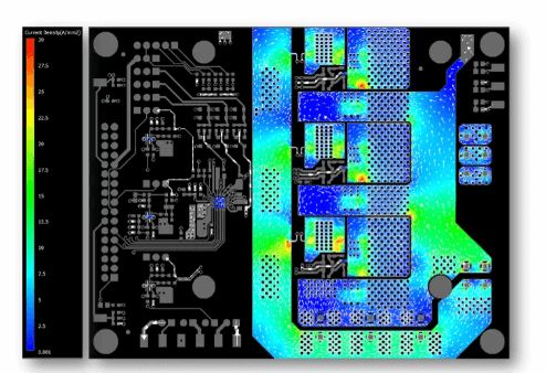
4. Measurement and Simulation Results
To quantify these relationships, we conducted both simulations and physical measurements on test boards with varying via arrangements:
4.1 Test Vehicle Design
We designed a series of test boards with:
- 6-layer stackup (1.6mm total thickness)
- Various via arrangements (grid, staggered, peripheral)
- Via diameters ranging from 0.2mm to 0.5mm
- Via counts from 4 to 64 per thermal pad
- Spacing from 0.5mm to 2mm center-to-center
4.2 Measurement Methodology
ESR and ESL were measured using:
- Vector Network Analyzer (VNA) for frequency-domain impedance analysis
- Time-domain reflectometry (TDR) for characteristic impedance
- Four-point probe measurements for DC resistance
4.3 Key Findings
- ESR vs. Via Count: ESR follows the expected 1/n relationship for up to ~16 vias, beyond which diminishing returns are observed due to non-uniform current distribution.
- ESL vs. Spacing: ESL reduction with increased via count is highly dependent on spacing. At 0.5mm spacing, 16 vias provided only 40% of the expected ESL reduction due to mutual inductance effects.
- Pattern Comparison: Staggered patterns showed 15-20% lower ESL than grid patterns with equivalent via count and spacing, while maintaining similar ESR.
- Diameter Impact: Increasing via diameter from 0.3mm to 0.5mm reduced single-via ESR by 65% and ESL by 30%, but required 2.8× more board area.
- Frequency Effects: Above 1MHz, skin effect caused ESR to increase by up to 300% for small-diameter vias (0.2mm), while larger vias (0.5mm) showed only 150% increase.
5. Design Guidelines
Based on our findings, we recommend the following design guidelines for thermal loop PCBs:
- Via Count: Use between 8-16 vias for most power device footprints (5mm×5mm to 10mm×10mm). Additional vias provide limited benefit.
- Arrangement Pattern: Prefer staggered patterns over simple grids for better ESL performance without sacrificing ESR.
- Spacing: Maintain 0.8-1.2mm center-to-center spacing to balance mutual inductance effects with board area utilization.
- Diameter Selection: Choose the largest via diameter that fits within pad constraints, preferably ≥0.3mm for power applications.
- Thermal-Electrical Balance: For applications where thermal requirements dominate, increase via count before increasing diameter to preserve board space.
- High-Frequency Designs: For switching frequencies above 1MHz, prioritize ESL reduction through careful via arrangement over minimal ESR improvement.
6. Conclusion
This study demonstrates that via arrangement in thermal loop PCBs significantly impacts both ESR and ESL characteristics. While increasing via count generally improves both thermal and electrical performance, the relationship is non-linear due to mutual inductance effects and current distribution non-uniformities. Staggered via patterns emerge as particularly effective for minimizing ESL while maintaining low ESR. Designers must carefully consider the trade-offs between via count, arrangement pattern, and geometric parameters to optimize both thermal and electrical performance for their specific application requirements.
Future work could explore more complex via arrangements using machine learning optimization techniques, as well as the impact of asymmetric via distributions for devices with non-uniform heat generation patterns. Additionally, the interaction between via arrangements and different PCB dielectric materials warrants further investigation.