The Rigid-Flex Fabrication Process
Prior to the commencement of the rigid-flex fabrication process, there is a PCB design layout stage. Once the layout is fixed, the rigid-flex fabrication process begins.
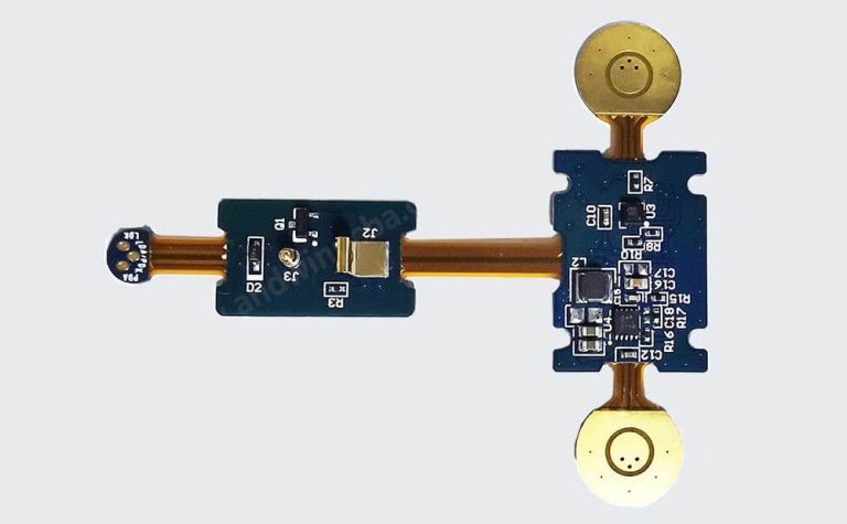
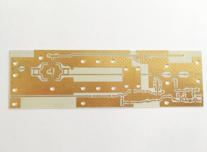
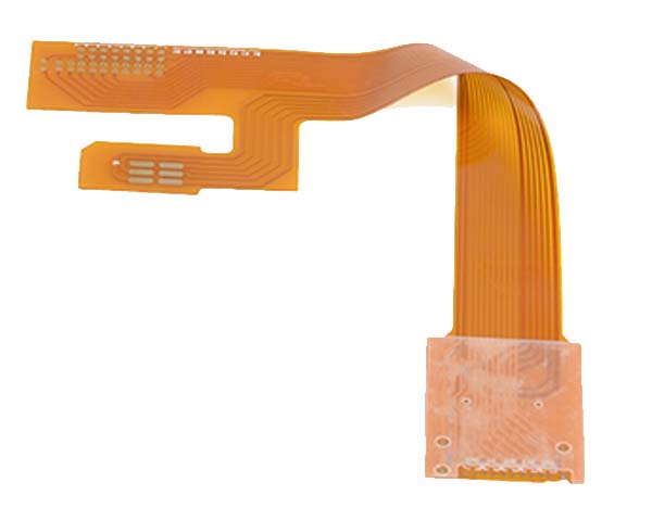
The rigid-flex fabrication process combines rigid and flexible board manufacturing technologies. These boards stack up layers of rigid and flexible PCBs.
The components are assembled in rigid areas and the interconnection to neighboring rigid boards is made via flexible areas. The connection between the layers is introduced through plated through holes.

Rigid-flex fabrication involves the following steps:
1.Preparation of base material: The rigid-flex fabrication process starts with the preparation or cleaning of laminate. The laminate containing the copper layer with or without adhesive coating is pre-cleaned before other fabrication processes.
2.Pattern generation: Accomplished through either screen printing or photo imaging.
3.Etching process: Both sides of the lamination containing the circuit pattern are etched by either dipping in an etch bath or by spraying an etchant solution.

4.Mechanical drilling process: The circuit holes, pads, and via patterns required in the production panels are drilled using precision drilling systems or techniques. For example, the laser drilling technique.
5.Copper plating process: The copper plating process focuses on depositing required copper inside the plated through holes to establish the electrical interconnection between the rigid-flex board layers.
6.Cover lay application: The cover lay material, usually polyimide film, and the adhesive are imprinted on the surface of the rigid-flex board using screen printing.
7.Cover lay lamination: The proper adhesion of the cover lay is ensured by laminating it under specified limits of heat, pressure, and vacuum.
8.Application of stiffener: If required as per the design of the rigid-flex boards, localized additional stiffeners are applied prior to the additional lamination process.
9.Flex board cutting: Hydraulic punching methods or specialized blanking knives are used for cutting the flex board from the production panel.
10.Electrical testing and verification: Rigid-flex boards are electrically tested as per IPC-ET-652 guidelines to confirm that the isolation, continuity, quality, and performance of the boards meet the design specifications. Testing methods include flying probes and grid testing systems.
The rigid-flex fabrication process is ideal for the construction of circuits in the medical, aerospace, military, and telecommunication industries, as these boards offer great performance and precise functioning, especially in harsh environments.
To design sturdy rigid-flex boards for extreme conditions, Cadence’s suite of design and analysis tools can be used.