The Role and Design of PCB Serpentine Traces
Abstract
This comprehensive article explores the critical role of serpentine traces in modern printed circuit board (PCB) design and provides detailed guidance on their implementation. Covering signal integrity considerations, timing compensation techniques, and practical design methodologies, this paper serves as a technical reference for PCB designers working with high-speed digital systems. The discussion includes the fundamental purposes of serpentine routing, various implementation approaches, and best practices for maintaining signal quality while achieving timing objectives.
1. Introduction to Serpentine Traces
Serpentine traces, also known as meander or tuned delay lines, represent a fundamental routing technique in modern PCB design. These intentionally serve multiple purposes in high-speed digital circuits where signal timing relationships prove critical to proper system operation.
1.1 Definition and Basic Characteristics
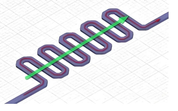
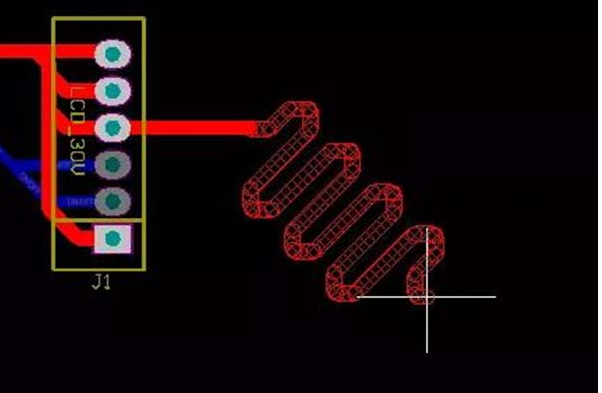
A serpentine trace consists of a conductor pattern that deliberately incorporates alternating directional changes to increase the total propagation path length between two points on a PCB. Unlike straight-line routing that minimizes trace length, serpentine patterns add controlled length while conserving board space through compact, repeating geometric patterns.
1.2 Historical Context
The use of serpentine routing emerged as digital systems transitioned from purely asynchronous designs to synchronous architectures with clock frequencies exceeding tens of megahertz. Early computer systems in the 1980s first employed these techniques to address growing timing challenges, with applications expanding significantly as processor speeds increased exponentially following Moore’s Law.
2. Primary Functions of Serpentine Traces
2.1 Signal Delay Matching
The predominant application of serpentine traces involves delay matching between related signals in parallel bus architectures or differential pairs. In synchronous systems, all signals within a group must arrive within a specified timing window to ensure proper operation.
Critical applications include:
- Memory interfaces (DDR, LPDDR)
- High-speed serial links with multiple lanes
- Clock distribution networks
- Differential pair length matching
2.2 Timing Compensation
Serpentine routing enables precise adjustment of signal propagation times to compensate for:
- Clock skew in distribution networks
- Variability in driver/receiver characteristics
- Path length differences in branched networks
2.3 Impedance Continuity Maintenance
Properly designed serpentine patterns can maintain consistent characteristic impedance along the entire trace length, unlike alternative length-matching methods that might introduce impedance discontinuities.
3. Electrical Considerations
3.1 Propagation Delay Fundamentals
The propagation delay (tpd) of a PCB trace depends on the effective dielectric constant (εeff) of the surrounding material and the speed of light (c):
tpd = (L × √εeff) / c
Where L represents the physical trace length. Typical FR4 materials (εr ≈ 4.3) yield propagation delays of approximately 140-170 ps/inch (55-67 ps/cm).
3.2 Signal Integrity Implications
Serpentine routing introduces several signal integrity considerations:
3.2.1 Crosstalk
Tightly spaced parallel segments in serpentine patterns create opportunities for capacitive and inductive coupling. The 3W rule (maintaining at least three times the trace width between parallel segments) helps mitigate this effect.
3.2.2 Impedance Discontinuities
Sharp corners can cause impedance variations. Best practices recommend:
- Using 45° miters for directional changes
- Maintaining constant trace width throughout
- Avoiding acute angle turns
3.2.3 Radiation Effects
The periodic structure of serpentine traces can act as an unintentional antenna. Ground shielding and proper termination help control electromagnetic emissions.
4. Serpentine Trace Design Methodologies
4.1 Basic Geometric Parameters
Key dimensions in serpentine design include:
- Amplitude (A): The perpendicular distance between parallel segments
- Corner spacing (S): The distance between directional changes
- Segment length (L): The straight portion between bends
4.2 Common Pattern Types
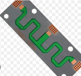
4.2.1 Standard Serpentine
Alternating 90° turns create a rectangular waveform pattern. This offers the highest length density but requires careful crosstalk management.
4.2.2 Tapered Serpentine
Gradually changing amplitudes help distribute discontinuities and reduce resonant effects.
4.2.3 Circular Arc Serpentine
Using curved segments instead of angled turns minimizes impedance discontinuities.
4.3 CAD Implementation Techniques
Modern PCB design software provides multiple approaches to serpentine routing:
4.3.1 Manual Routing
Designers manually place segments while monitoring length reports. This offers maximum control but requires significant time investment.
4.3.2 Automated Length Tuning
Most professional PCB tools (Altium, Cadence, Mentor) include automated serpentine routing features that:
- Calculate required additional length
- Insert appropriate patterns
- Maintain design rule compliance
4.3.3 Parametric Cells
Reusable serpentine modules with adjustable parameters ensure consistency across designs.
5. Practical Design Guidelines
5.1 Determining Required Length
The additional trace length (ΔL) needed for timing compensation derives from:
ΔL = c × Δt / √εeff
Where Δt represents the required delay adjustment.
5.2 Spacing Considerations
5.2.1 Inter-segment Spacing
Maintain minimum spacing of:
3× trace width (3W rule) for typical designs
5× trace width for sensitive high-speed signals
5.2.2 Via Clearance
Ensure adequate clearance when serpentines transition between layers.
5.3 Layer Stackup Implications
Preferred approaches:
- Route serpentines on layers adjacent to solid reference planes
- Avoid crossing plane splits or gaps
- Consider differential pair serpentines as coupled units
5.4 Manufacturing Constraints
Account for fabrication capabilities:
- Minimum bend radii
- Etching tolerances
- Copper grain direction effects
6. Advanced Applications
6.1 DDR Memory Interfaces
Modern memory systems require precise length matching:
- Data lines to DQS strobes (typically ±50ps)
- Address/command lines to clocks (typically ±100ps)
6.2 Multi-Gigabit Serial Links
Parallel serial channels (PCIe, SATA) often need lane-to-lane skew compensation at the physical layer.
6.3 RF and Microwave Applications
Controlled serpentine patterns serve as:
- Distributed elements in filters
- Artificial transmission lines
- Delay elements in phased array systems
7. Simulation and Verification
7.1 Pre-layout Analysis
Use electromagnetic simulation tools to:
- Predict impedance characteristics
- Analyze coupling effects
- Verify timing adjustments
7.2 Post-layout Verification
Critical checks include:
- Signal integrity simulations (eye diagrams, TDR)
- Timing analysis with extracted parasitics
- Manufacturability review (DFM)
8. Common Pitfalls and Solutions
8.1 Excessive Length Matching
Over-compensation can:
- Increase susceptibility to noise
- Create unnecessary board area consumption
- Degrade signal quality
Solution: Implement just-enough compensation using accurate delay calculations.
8.2 Improper Return Paths
Discontinuous reference planes under serpentines cause:
- Impedance variations
- Increased radiation
- Signal quality degradation
Solution: Maintain unbroken reference planes and provide adequate return vias.
8.3 Resonance Effects
Periodic structures can create standing waves at certain frequencies.
Solution: Use non-uniform patterns or damping techniques for critical applications.
9. Future Trends
Emerging technologies influencing serpentine routing include:
- 3D printed electronics with conformal routing
- Terahertz frequency interconnects
- Photonic integrated circuits with optical delay lines
- AI-assisted routing optimization
10. Conclusion
PCB serpentine traces remain an essential tool for modern electronic design, enabling precise timing control in increasingly complex high-speed systems. By understanding the underlying principles and applying disciplined design practices, engineers can effectively implement these structures while maintaining signal integrity and manufacturability. As data rates continue to escalate, the thoughtful application of serpentine routing techniques will remain critical to successful PCB implementation across numerous applications.