Thermal Analysis of Encapsulated PCB Systems: A Comprehensive Review
Abstract
The rapid advancement of electronic devices has led to increased power densities and miniaturization, making thermal management a critical aspect of Printed Circuit Board (PCB) design. Encapsulation, used for protection against environmental factors, further complicates heat dissipation. This paper provides a comprehensive review of thermal analysis techniques for encapsulated PCB systems, covering modeling approaches, material considerations, simulation methods, and experimental validation. The challenges and future trends in thermal management of encapsulated PCBs are also discussed.
1. Introduction
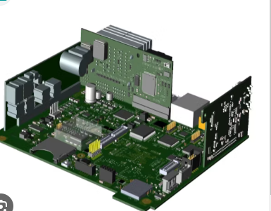
Encapsulated PCB systems are widely used in automotive, aerospace, consumer electronics, and industrial applications to protect circuitry from moisture, dust, and mechanical stress. However, encapsulation materials, typically polymers like epoxy resins or silicones, have low thermal conductivity, leading to heat accumulation and potential reliability issues. Effective thermal analysis is essential to ensure optimal performance and longevity of encapsulated PCBs.
This review explores:
- Heat generation mechanisms in PCBs
- Thermal modeling techniques
- Material selection for encapsulation
- Simulation and experimental validation methods
- Emerging trends in thermal management
2. Heat Generation in PCBs
Heat in PCBs primarily originates from:
- Active components (CPUs, GPUs, power ICs)
- Passive components (resistors, inductors)
- High-frequency signal losses (skin effect, dielectric losses)
- Current crowding in traces
Encapsulation compounds, while providing mechanical and environmental protection, often act as thermal insulators, exacerbating temperature rise. Understanding heat generation and dissipation pathways is crucial for accurate thermal analysis.
3. Thermal Modeling Approaches
3.1 Analytical Models
- Lumped Parameter Models: Simplified representations using thermal resistances and capacitances.
- Fourier’s Law: Used for steady-state heat conduction analysis.
- Finite Difference Method (FDM): Discretizes the PCB into nodes for numerical solutions.
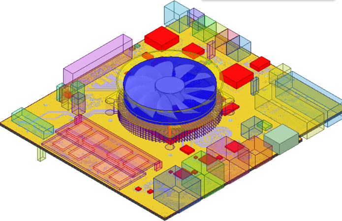
3.2 Numerical Methods
- Finite Element Analysis (FEA): COMSOL, ANSYS, and other tools simulate heat distribution.
- Computational Fluid Dynamics (CFD): Models convective cooling effects.
- Multi-Physics Simulations: Couples thermal, electrical, and mechanical analyses.
3.3 Equivalent Thermal Circuit Models
- Represents heat flow using electrical analogies (resistors for thermal resistance, capacitors for thermal capacitance).
- Useful for quick estimations but lacks spatial resolution.
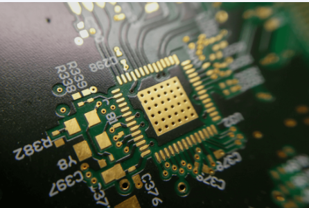
4. Encapsulation Materials and Thermal Properties
Key material properties affecting thermal performance:
- Thermal Conductivity (k): Higher k improves heat dissipation (e.g., alumina-filled epoxies).
- Coefficient of Thermal Expansion (CTE): Mismatch with PCB materials induces mechanical stress.
- Glass Transition Temperature (Tg): Determines thermal stability.
Common encapsulation materials:
- Epoxy Resins: Low k (~0.2 W/mK), widely used due to cost and adhesion.
- Silicones: Flexible, moderate k (~0.5 W/mK), good for high-temperature applications.
- Thermally Conductive Fillers: Alumina, boron nitride, and graphene enhance k.
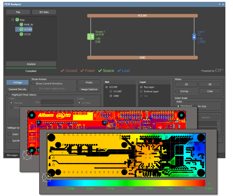
5. Simulation Techniques for Encapsulated PCBs
5.1 Steady-State vs. Transient Analysis
- Steady-State: Evaluates temperature distribution at equilibrium.
- Transient: Assesses thermal response over time (critical for pulsed operation).
5.2 Boundary Conditions
- Conduction: Heat transfer through PCB layers and encapsulation.
- Convection: Natural or forced airflow cooling.
- Radiation: Minor role in most encapsulated systems.
5.3 Software Tools
- ANSYS Icepak: CFD-based thermal simulation.
- COMSOL Multiphysics: Multi-domain thermal analysis.
- SolidWorks Flow Simulation: Integrated thermal-fluid modeling.
6. Experimental Validation
6.1 Infrared Thermography
- Non-contact temperature mapping.
- Limitations with opaque encapsulation.
6.2 Thermocouples and RTDs
- Direct temperature measurement at critical points.
- Intrusive and may affect thermal behavior.
6.3 Thermal Test Dies
- Dedicated ICs for measuring junction temperatures.
6.4 Accelerated Life Testing
- Evaluates long-term reliability under thermal cycling.
7. Challenges in Thermal Analysis of Encapsulated PCBs
- Material Heterogeneity: Composite structures complicate modeling.
- Interface Resistance: Poor thermal contact between layers.
- Aging Effects: Degradation of encapsulation over time.
- Trade-offs: Mechanical protection vs. thermal performance.
8. Emerging Trends and Solutions
- Nano-Enhanced Encapsulants: Carbon nanotubes (CNTs) and graphene improve k.
- Phase Change Materials (PCMs): Absorb and dissipate heat efficiently.
- 3D Printing of Encapsulation: Customized thermal pathways.
- Machine Learning for Thermal Optimization: AI-driven design improvements.
9. Conclusion
Thermal analysis of encapsulated PCB systems is crucial for ensuring reliability and performance. While encapsulation provides necessary protection, it introduces thermal management challenges. Advanced modeling techniques, improved materials, and experimental validation are key to overcoming these issues. Future research should focus on high-conductivity encapsulants, multi-physics optimization, and AI-assisted thermal design.