What Is a Beveler in PCB Manufacturing?
Introduction to PCB Beveling
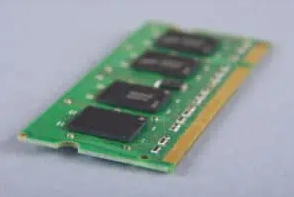
In the world of printed circuit board (PCB) manufacturing, beveling is a critical edge preparation process that ensures proper connector mating and improves the overall reliability of the finished product. A beveler is a specialized machine or tool used to create precise angled edges on PCBs, particularly for boards that will be used in edge-card applications or require specific edge profiles for assembly purposes.
PCB beveling serves multiple functions in electronics manufacturing. It facilitates the smooth insertion of circuit boards into edge connectors, prevents damage to connector contacts during insertion/removal, and enhances the overall mechanical integrity of the board’s edges. The beveling process is especially important for high-density interconnect (HDI) boards and those used in demanding applications where precise mechanical tolerances are required.
Understanding Beveler Machines
Types of PCB Bevelers
PCB bevelers come in various configurations to accommodate different production needs:
- Manual Bevelers: Simple hand-operated tools used for low-volume production or prototyping. These require operator skill to maintain consistent angles.
- Semi-Automatic Bevelers: Combine manual loading with automated beveling processes, offering a balance between productivity and cost.
- Fully Automatic Bevelers: High-production machines that handle loading, positioning, beveling, and unloading with minimal operator intervention.
- CNC Bevelers: Computer numerically controlled machines that offer programmable angle adjustments and high precision for complex beveling requirements.
Key Components of a Beveler Machine
A typical PCB beveler consists of several essential components:
- Cutting Head: Contains the rotating cutter that creates the beveled edge
- Angle Adjustment Mechanism: Allows precise setting of the bevel angle
- Board Holding/Fixturing System: Secures the PCB during the beveling process
- Dust Collection System: Removes fiberglass and copper particles generated during cutting
- Control Panel: Interface for operator control and parameter setting
- Feed Mechanism: Advances the board through the cutting area (in automatic models)
The Beveling Process in PCB Manufacturing
Step-by-Step Beveling Procedure
- Board Preparation: The PCB must be properly routed or scored before beveling to ensure clean edges.
- Machine Setup: The beveler is configured with the appropriate angle (typically 30° or 45°), depth, and feed rate based on the PCB specifications.
- Board Loading: The operator or automated system positions the PCB against the guide fence, ensuring proper alignment.
- Bevel Cutting: The rotating cutter removes material from the PCB edge at the predetermined angle, creating a smooth, consistent chamfer.
- Quality Check: The beveled edge is inspected for angle accuracy, smoothness, and freedom from chips or burrs.
- Cleaning: Any residual dust or debris is removed from the board before further processing.
Common Bevel Angles in PCB Manufacturing
The most frequently used bevel angles in PCB production are:
- 30° Bevel: Common for standard edge card connectors
- 45° Bevel: Used for many industrial and military applications
- 20° Bevel: Found in some specialized connector systems
- Custom Angles: Designed for proprietary connector configurations
The choice of angle depends on the specific connector requirements and the intended application of the PCB.
Importance of Beveling in PCB Production
Mechanical Advantages
Proper beveling provides several mechanical benefits:
- Easier Insertion: The angled edge guides the PCB smoothly into edge connectors, reducing insertion force.
- Reduced Wear: Prevents scraping of connector contacts during repeated insertions and removals.
- Improved Alignment: Helps maintain proper board-to-connector orientation.
- Edge Protection: Removes sharp edges that could cause injury or damage to other components.
Electrical Considerations
While primarily a mechanical process, beveling affects electrical performance in several ways:
- Contact Reliability: Ensures consistent pressure between edge contacts and connector pins.
- Signal Integrity: Proper beveling prevents edge damage that could affect high-speed signals.
- Impedance Control: Maintains consistent trace geometry up to the board edge.
Quality and Reliability Factors
Beveling contributes to overall PCB quality by:
- Extending Connector Life: Reduces wear on both the PCB and mating connector.
- Improving Durability: Eliminates edge defects that could lead to delamination or cracking.
- Enhancing Aesthetics: Provides a professional, finished appearance to the board edges.
Technical Specifications of PCB Bevelers
Key Performance Parameters
When selecting or operating a PCB beveler, several technical specifications must be considered:
- Bevel Angle Range: The range of angles the machine can produce (typically 15°-60°)
- Board Thickness Capacity: The minimum and maximum PCB thickness the machine can handle
- Cutting Accuracy: The angular tolerance (usually ±0.5° or better)
- Surface Finish Quality: Measured in terms of roughness or visual inspection criteria
- Production Speed: Typically measured in meters per minute of edge processed
- Maximum Board Dimensions: The largest PCB size the machine can accommodate
Material Considerations
PCB bevelers must handle various board materials:
- FR-4 Standard: The most common PCB substrate material
- High-Tg Materials: More challenging to bevel due to increased hardness
- Metal-Core Boards: Require specialized cutters and higher machine rigidity
- Flex Circuits: Demand precise control to prevent delamination or tearing
Advanced Beveling Techniques
Precision Beveling for High-Density Applications
Modern electronics demand increasingly precise beveling for:
- Fine-Pitch Connectors: Require exacting edge profiles for proper contact alignment
- Backplane Systems: Where multiple boards must mate perfectly in high-density configurations
- RF/Microwave PCBs: Edge quality affects signal performance at high frequencies
Laser Beveling Technology
Emerging laser beveling systems offer advantages for certain applications:
- Contactless Processing: Eliminates mechanical stress on the PCB
- Higher Precision: Can achieve tighter tolerances than mechanical cutting
- Complex Profiles: Capable of creating non-linear or customized edge shapes
However, laser systems currently have limitations in production speed and cost compared to traditional mechanical bevelers.
Maintenance and Operation of PCB Bevelers
Routine Maintenance Requirements
To ensure consistent performance, bevelers require:
- Cutter Maintenance: Regular sharpening or replacement of cutting tools
- Lubrication: Proper lubrication of moving parts as specified by the manufacturer
- Alignment Checks: Periodic verification of angle accuracy and fence alignment
- Dust Collection System: Regular cleaning and filter replacement
- Mechanical Inspection: Checking for wear on guides, bearings, and other components
Operator Training Considerations
Effective beveler operation requires training in:
- Machine Setup: Proper installation of cutters and angle adjustment
- Material Handling: Correct loading and positioning of PCBs
- Quality Inspection: Recognizing acceptable versus defective bevels
- Safety Procedures: Proper use of guards and personal protective equipment
Quality Control in PCB Beveling
Inspection Methods
Several techniques are used to verify bevel quality:
- Visual Inspection: Checking for chips, burns, or rough surfaces
- Angle Measurement: Using precision protractors or optical comparators
- Dimensional Verification: Confirming bevel width and depth meet specifications
- Functional Testing: Test-fitting boards into mating connectors
Common Defects and Their Causes
Typical beveling defects include:
- Uneven Angles: Caused by worn cutters or misalignment
- Edge Chipping: Resulting from dull tools or improper feed rates
- Burn Marks: From excessive heat due to high RPM or slow feed
- Inconsistent Depth: Due to uneven board thickness or fixturing problems
Applications of Beveled PCBs
Common Use Cases
Beveled edges are essential for:
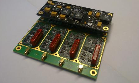
- Edge Card Connectors: Found in many computer and industrial applications
- Backplane Systems: Where multiple boards connect perpendicularly
- Module Insertion: For cards that plug into larger systems
- Test Fixtures: Where repeated insertion is required
Industry-Specific Requirements
Different industries have particular beveling needs:
- Aerospace: Strict tolerances and reliability requirements
- Medical: Clean edges to prevent particle generation
- Automotive: Vibration-resistant edge profiles
- Telecommunications: High-frequency signal integrity considerations
Future Trends in PCB Beveling Technology
Automation Integration
Modern bevelers are increasingly being integrated with:
- Automated Optical Inspection (AOI): For inline quality verification
- Robotic Handling Systems: For complete automation of loading/unloading
- Industry 4.0 Connectivity: For data collection and process optimization
Advanced Material Processing
Emerging needs include:
- Ceramic Substrates: Requiring specialized beveling approaches
- Ultra-Thin PCBs: Demanding precise control to prevent warping or damage
- High-Speed Materials: With unique cutting characteristics
Conclusion
The PCB beveler plays a vital role in modern electronics manufacturing, ensuring reliable connections and professional-quality board edges. As PCBs continue to evolve with higher densities and more demanding applications, beveling technology must advance accordingly. Understanding the principles, equipment, and processes involved in PCB beveling helps manufacturers produce higher quality products and select the appropriate beveling solutions for their specific needs.
From simple manual tools to sophisticated CNC systems, bevelers remain an essential part of the PCB fabrication process, bridging the gap between board manufacturing and final assembly. Proper implementation of beveling techniques contributes significantly to the reliability, durability, and performance of electronic devices across all industries.