What is hardware design?
My understanding: Hardware design is to complete hardware products (note: products, not development boards) that meet the requirements of PRS (Product Requirement Specification) and COGS (Cost of Goods Sale) within the specified time using the current mature chip solutions or technologies in the industry, including functions, performance, power supply, power consumption, heat dissipation, noise, signal integrity, electromagnetic radiation (EMC/EMI), safety, component sourcing, reliability, testability (DFT: design for test), and manufacturability (DFM: design for manufacture).
It can be seen that for a successful hardware design, the realization of the main functions is only a small part of all the links, and basically speaking, the realization of the main functions mainly depends on the chip package provided by the chip manufacturer. Generally speaking, in order to reduce the risk, it is mainly completed by referring to the reference design of the chip package. The chip manufacturer will also provide all the information including device packaging, reference design, simulation model, PCB reference, etc. Today, the chip functions are becoming more and more complex. A chip has hundreds or thousands of PINs. For a new project, there is no time to thoroughly understand each PIN, the specific function of each input and output, and the electrical parameters page by page, especially for high-speed design, such as DDR3 interface, XAUI interface, etc. Generally speaking, the reference design provided by the chip manufacturer is the best solution they have developed, verified, and tested. In many cases, you must follow the reference design, otherwise the hardware may have problems, generally speaking, signal integrity problems or EMC problems.
Chip manufacturers provide more and more thoughtful services. It seems that the value of hardware engineers HW (Hardware Engineer) is getting lower and lower. After all, the core functions or technologies of a product are generally in ASIC or FPGA. HW generally does not have the ability to carry out core logic design IC design. After all, this is another work that runs in parallel with HW design, and it is also a very complicated work. I have also been confused about this problem. I always feel that there is nothing to do with hardware design. Isn’t it just copying reference designs, just like assembling a single board like assembling a computer? Of course, with the increase of project experience, especially in the role of hardware system-level design now, I feel that I used to consider more from the perspective of a schematic design engineer. As I said at the beginning, for a successful hardware design, function Function is only a small part. As for other factors and capabilities, the ability of a HW depends on the more factors that can be considered, the deeper it is, the better it is a HW engineer.

1.Cost Cost:
The main profit of any company that sells hardware products is generally the sales price-COGS, and 90% of COGS depends on the design, and the rest is the production cost. This price is generally more transparent, there are many foundries, and the competition is fierce. Although 60% of the design cost also depends on the price of the main chip (this mainly depends on the negotiation between the company’s senior management and the chip manufacturer, the role of HW is limited, and it is more the system engineer who makes the decision on which chip to use to meet the product requirements and software function requirements), the remaining resistors, capacitors, inductors, diodes, transistors, protection devices, interface devices, logic chips, logic functions, small chips, and power circuits are all decided by HW. Of course, there are reference designs, but generally speaking, in order to better reflect the good performance of the chip, the reference design will generally use more expensive and better-performing devices, which requires a trade-off based on the company’s device library. My experience is to look at the company’s similar product designs and see what devices are used by the mainstream. After all, for components, the price has a lot to do with the purchase volume, and the price caused by different purchase volumes may differ by several times.
2.Signal Integrity:
It mainly affects two aspects: EMC and timing. A bad SI design will have strong overshoot/undershoot and spikes, which will cause the emission of the corresponding frequency N resonant frequency; a bad SI design will lead to High/low instability, or the rising time/falling time RisingTime/FallingTime takes up too long a data cycle, or the clock is unstable, which will lead to misjudgment when sampling the sample at the receiving end. In fact, the receiving end will not make mistakes, only the signal will make mistakes. SI design in schematic design is mainly solved from the impedance matching (serial resistance), supplemented by appropriate decoupling filter capacitors; it is mainly on the PCB. Generally speaking, the more PCB layers, the better the SI will be. Of course, there is a trade-off with Cost here.
3.Power Supply Design:
Although generally larger companies have dedicated power design engineers, basic power design capabilities are still very important for HW. In theory, any circuit is a power supply, and any circuit problem can be attributed to a power supply problem. Only when you have a deep understanding of the power supply circuit can you understand and deepen the circuit board, especially for analog circuit problems, you can think of using analog circuits to design some simple circuits instead of laboriously using logic circuits.
4.Safety:
For interface circuits, the main cost is in safety devices. How much voltage and current should this interface withstand? This requires careful consideration of what devices to use, fuse? PTC? TVS? High-voltage capacitor?
5.Electromagnetic compatibility EMC/EMI:
It is mainly aimed at the corresponding regulations of various countries (safety regulations are also), and decoupling and filtering are fully considered for various signals that may generate radiation. For the EU, it is generally EN55022/EN55024, and for the United States, it is generally FCC Part 15. The radiation standards of the EU and the United States are slightly different, and the EU standards are slightly stricter.
6.Power consumption:
Nowadays, environmental protection is advocated, and so are operators. HW must also consider power saving, such as using more efficient power supply circuits, replacing LDO with PWM, and more efficient conversion topologies.
7.Thermal/Cooling:
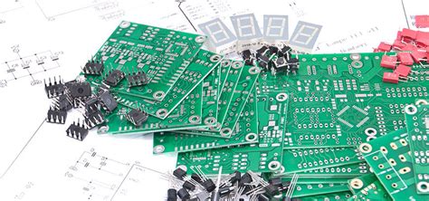
The chip integration is getting higher and higher. The power consumption of a single chip has increased from a few watts to dozens of watts now. Thermal dissipation is a big problem. Moreover, with the increase in the interface rate, the power consumption of the interface chip is also increasing, causing the entire system to be: hot! This requires careful consideration of the thermal problem, from the layout of the PCB, to the use of the heat sink, to the use of the fan, there are many considerations.
8.Noise:
The fan is the best way to dissipate heat, but the problem it brings is noise. The ITU also has clear specifications for the noise of communication equipment, which requires balancing the number of fans, speed, wind direction, control and other factors.
9.Component Sourcing:
The components selected by HW must be available from the Sourcing department, and generally the second source and lead time issues must also be considered. You cannot choose a rare component produced by only a small company. What if the component is EoL? You can only modify the design, which is a big loss!
10.Reliability:
What is the MTBF value of the entire system? What is the device with the greatest risk? What is the working margin of each device?
11.Testability (DFT: design for test)/manufacturability (DFM: design for manufacture):
Mainly for factory considerations, it must be considered to facilitate the factory’s production testing and production. If your test is very complicated, it will greatly reduce the production capacity and yield of the production line, thereby affecting the supply and production of finished products.
For reference designs, I feel that the most useful parts are mainly power supply circuits, decoupling filter circuits and layout design. As for bus connections, reset circuits, clock circuits, interface circuits, etc., generally speaking, they need to be modified according to the company’s device library, design cases and mainstream devices/solutions in the industry. So don’t be superstitious about reference circuits, they are just references. If you are overly superstitious about reference designs, and you copy the chip before you understand its specific functions/parameters, even if it works, there will definitely be many problems in terms of cost and production.

