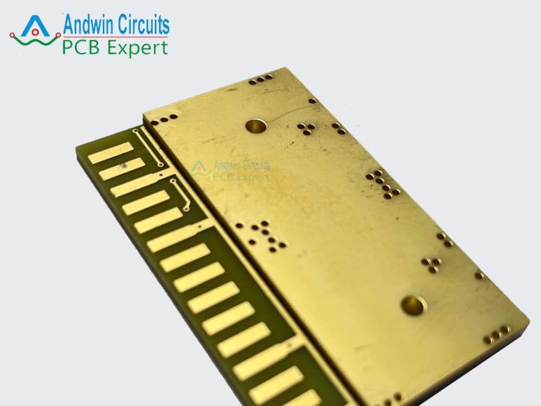
8 bit computer pcb
Detailed Guide to Building 8-bit Computer PCB.
Detailed Guide to Building 8-bit Computer PCB needs to be discussed in detail from multiple aspects.
First, it is crucial to understand the basic architecture of 8-bit computers.
8-bit computers are usually composed of basic components such as central processing unit (CPU), memory, input and output (I/O) interface and clock circuit. Each component plays a key role in the overall function of the computer, so special attention needs to be paid to the layout and connection of these components when designing the PCB.
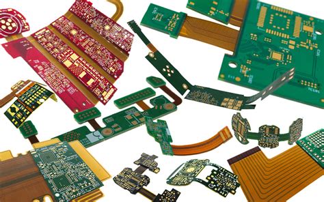
Next, choosing the right components is the basis for successfully building an 8-bit computer PCB.
Common 8-bit CPUs include Intel 8080, Zilog Z80 and MOS 6502, etc. After selecting a suitable CPU, it is also necessary to select memory chips, I/O interface chips and other auxiliary chips that are compatible with it. Make sure that the specifications and pinouts of these components meet the design requirements so that the correct connection can be achieved on the PCB.
After the component selection is completed, circuit design is the next key task.
Using electronic design automation (EDA) software such as Eagle, KiCad or Altium Designer can help designers draw circuit schematics and generate PCB layouts. When drawing the circuit schematic, special attention should be paid to the wiring of the power and ground lines to ensure the stability and reliability of the circuit. In addition, the wiring of the signal lines also needs to follow certain rules to avoid signal interference and crosstalk.

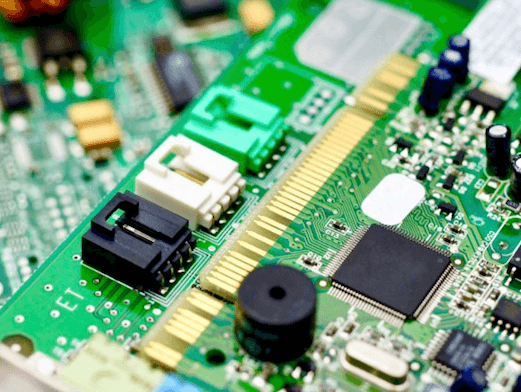
After completing the circuit design, PCB layout is an important step.
PCB layout needs to consider the physical size and pin arrangement of components to ensure that all components can be properly installed and connected. Reasonable layout can reduce signal delay and interference and improve the overall performance of the circuit. During the layout process, attention should also be paid to heat dissipation, especially for components with high power consumption, which can be improved by adding heat dissipation holes or heat sinks.
After the PCB layout is completed, electrical rule checking (ERC) and design rule checking (DRC) are key steps to ensure the correctness of the design. ERC can check whether the electrical connection in the circuit schematic is correct, while DRC can check whether the design rules in the PCB layout meet the manufacturing requirements. Through these checks, errors in the design can be found and corrected to ensure that the final PCB can work properly.
Finally, choosing a suitable PCB manufacturer for production is the last step to realize the design.
Choosing a manufacturer with a good reputation and quality assurance can ensure the manufacturing quality and delivery time of the PCB. When submitting a manufacturing order, you need to provide complete design files, including circuit schematics, PCB layout diagrams, and component lists.
In summary, building an 8-bit computer PCB requires detailed planning and execution of multiple links from component selection, circuit design, PCB layout, electrical rule checking to final manufacturing. Each link needs to be carefully considered and processed to ensure that the final PCB can meet the design requirements and work properly. Through a systematic design process and strict quality control, a high-performance 8-bit computer PCB can be successfully built.