Rf pcb layout book
Key Design Principles for RF PCB Layout
Designing a printed circuit board (PCB) for radio frequency (RF) applications is a complex task that requires a deep understanding of both electrical engineering principles and practical layout techniques.
The key design principles for RF PCB layout are crucial for ensuring optimal performance, minimizing interference, and achieving reliable operation. To begin with, one must consider the importance of impedance matching.
Impedance matching is essential in RF circuits to ensure maximum power transfer and minimize signal reflections. This involves carefully designing transmission lines and selecting appropriate components to match the impedance of the source, transmission line, and load.
Transitioning to another critical aspect, the layout of the ground plane plays a significant role in RF PCB design.
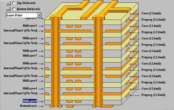
A continuous and unbroken ground plane helps to reduce noise and electromagnetic interference (EMI). It is advisable to use a solid ground plane on one layer of the PCB and ensure that all ground connections are made directly to this plane. This minimizes the loop area for return currents, thereby reducing the potential for EMI.
Moreover, the placement of components is another vital consideration.
In RF PCB design, components should be placed as close as possible to minimize the length of signal paths. This reduces the inductance and capacitance of the traces, which can otherwise degrade the signal integrity. Additionally, sensitive components should be isolated from noisy ones to prevent interference. For instance, placing RF components away from digital circuits can help in reducing cross-talk and noise coupling.
Furthermore, the routing of traces is a critical factor that cannot be overlooked.
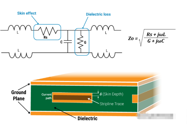
RF signals are highly susceptible to losses and interference, so it is essential to keep trace lengths as short as possible. When routing RF traces, it is beneficial to use microstrip or stripline techniques to control the impedance and maintain signal integrity. Additionally, avoiding sharp bends and right angles in traces can help in minimizing signal reflections and losses.
In addition to these principles, the use of proper shielding is indispensable in RF PCB design.
Shielding can be achieved through the use of metal enclosures or ground planes to protect sensitive components from external EMI. This is particularly important in high-frequency applications where even minor interference can significantly impact performance.
Another important consideration is the selection of materials.
The dielectric constant and loss tangent of the PCB material can affect the performance of RF circuits. Materials with low dielectric constant and low loss tangent are preferred for high-frequency applications as they help in maintaining signal integrity and reducing losses.
Moreover, thermal management is a crucial aspect that should not be neglected.
RF components can generate significant amounts of heat, which can affect their performance and reliability. Proper thermal management techniques, such as the use of thermal vias and heat sinks, should be employed to dissipate heat effectively.
Lastly, it is essential to perform thorough testing and validation of the RF PCB design.
This includes using network analyzers and spectrum analyzers to measure parameters such as return loss, insertion loss, and signal integrity. Testing helps in identifying and rectifying any issues that may arise during the design process, ensuring that the final product meets the desired specifications.
In conclusion, the key design principles for RF PCB layout encompass a range of considerations, from impedance matching and ground plane layout to component placement, trace routing, shielding, material selection, thermal management, and thorough testing. By adhering to these principles, designers can achieve optimal performance and reliability in their RF PCB designs.
Common Mistakes in RF PCB Layout and How to Avoid Them
Designing RF PCB layouts is a complex task that requires meticulous attention to detail and a deep understanding of electromagnetic principles. One of the most common mistakes in RF PCB layout is improper impedance matching. Impedance mismatches can lead to signal reflections, which degrade the performance of the RF circuit. To avoid this, designers should carefully calculate and maintain the characteristic impedance of transmission lines. Utilizing tools such as impedance calculators and simulation software can help ensure that the impedance is consistent throughout the layout.
Another frequent error is inadequate grounding.
A poor grounding scheme can result in increased noise and interference, which can severely impact the performance of RF circuits. To mitigate this, designers should use a solid ground plane and ensure that all ground connections are short and direct. Additionally, employing multiple vias to connect the ground plane to different layers can further enhance grounding effectiveness.
Component placement is another critical aspect where mistakes are often made.
Placing components too close to each other can lead to unwanted coupling and crosstalk, which can degrade signal integrity. To avoid this, designers should follow the principle of keeping high-frequency components and sensitive analog components well-separated. Furthermore, placing decoupling capacitors as close as possible to the power pins of active components can help filter out noise and stabilize the power supply.
Trace routing is another area where errors frequently occur.
Sharp bends in traces can cause signal reflections and impedance discontinuities. To prevent this, designers should use smooth, gradual curves instead of sharp angles when routing traces. Additionally, keeping trace lengths as short as possible can minimize signal loss and delay. When long traces are unavoidable, using differential pairs and controlled impedance routing can help maintain signal integrity.
Thermal management is often overlooked but is crucial for the reliable operation of RF circuits.
Inadequate thermal management can lead to overheating, which can cause components to fail or degrade over time. To address this, designers should incorporate thermal vias and heat sinks to dissipate heat effectively. Additionally, using thermal simulation tools can help identify potential hotspots and optimize the layout for better thermal performance.
Another common mistake is neglecting the effects of parasitic elements.
Parasitic capacitance and inductance can alter the behavior of RF circuits, leading to performance issues. To minimize parasitic effects, designers should keep traces and component leads as short as possible and avoid placing components too close to each other. Additionally, using ground planes and shielding can help reduce parasitic coupling.
Finally, insufficient testing and validation can lead to undetected issues that may only become apparent during production or field use.
To avoid this, designers should conduct thorough testing and validation at various stages of the design process. This includes using simulation tools to predict circuit behavior, performing prototype testing to identify and rectify issues, and conducting final validation to ensure the design meets all performance requirements.
In conclusion, avoiding common mistakes in RF PCB layout requires a comprehensive understanding of various design principles and meticulous attention to detail. By focusing on proper impedance matching, effective grounding, strategic component placement, careful trace routing, adequate thermal management, minimizing parasitic effects, and thorough testing, designers can significantly enhance the performance and reliability of their RF circuits. Employing these best practices will not only improve the quality of the final product but also streamline the design process, reducing the likelihood of costly revisions and delays.
Advanced Techniques for Minimizing Signal Interference in RF PCB Layout
In the realm of radio frequency (RF) printed circuit board (PCB) design, minimizing signal interference is paramount to ensuring optimal performance. Advanced techniques for mitigating such interference are essential for engineers striving to achieve high-fidelity signal transmission. One of the foremost strategies involves meticulous component placement. By strategically positioning components, designers can significantly reduce the potential for crosstalk and electromagnetic interference (EMI). For instance, placing sensitive analog components away from noisy digital circuits can help maintain signal integrity. Additionally, grouping components with similar functions together can further isolate potential sources of interference.
Transitioning to another critical aspect, the use of ground planes cannot be overstated.
A continuous ground plane provides a low-impedance path for return currents, thereby minimizing the loop area and reducing EMI. It is advisable to use a multilayer PCB design, where one or more layers are dedicated to ground planes. This not only enhances signal integrity but also aids in thermal management. Furthermore, ensuring that the ground plane is unbroken and avoiding splits can prevent the creation of unintended antennas that could radiate or pick up unwanted signals.
Another advanced technique involves the careful routing of traces.
High-frequency signals are particularly susceptible to interference, and thus, their traces should be kept as short and direct as possible. Employing differential pairs for high-speed signals can also be beneficial, as they help cancel out noise. Additionally, maintaining consistent trace impedance through controlled impedance routing is crucial. This can be achieved by carefully selecting the trace width and spacing, as well as the dielectric material of the PCB.
Moreover, the implementation of proper shielding techniques can further mitigate signal interference.
Shielding can be achieved through the use of metal enclosures or by incorporating shielding layers within the PCB itself. These shields act as barriers, preventing external EMI from affecting the sensitive circuitry. It is also important to ensure that the shields are properly grounded to avoid creating new sources of interference.
Transitioning to the topic of power supply design, it is essential to provide clean and stable power to the RF circuitry.
Power supply noise can easily couple into RF signals, leading to degradation in performance. Using low-noise voltage regulators and incorporating adequate decoupling capacitors can help filter out unwanted noise. Additionally, employing power planes instead of traces for power distribution can reduce impedance and minimize noise coupling.
Another advanced technique involves the use of vias.
Vias are used to connect different layers of a PCB, and their placement can significantly impact signal integrity. It is advisable to use multiple vias for ground connections to ensure a low-impedance path. Additionally, avoiding the use of vias in high-frequency signal paths can prevent signal degradation due to parasitic inductance and capacitance.
Lastly, simulation and modeling play a crucial role in minimizing signal interference in RF PCB layout.
Utilizing advanced simulation tools allows designers to predict and analyze potential sources of interference before the physical prototype is built. This proactive approach enables the identification and mitigation of issues early in the design process, saving time and resources.
In conclusion, minimizing signal interference in RF PCB layout requires a comprehensive approach that encompasses meticulous component placement, the use of ground planes, careful trace routing, proper shielding, clean power supply design, strategic via placement, and advanced simulation techniques. By employing these advanced techniques, engineers can achieve high-performance RF designs with minimal signal interference, ensuring reliable and efficient operation.
Essential Tools and Software for RF PCB Layout Design
Designing a Radio Frequency (RF) Printed Circuit Board (PCB) layout is a complex and meticulous process that requires a deep understanding of both the theoretical and practical aspects of RF engineering. To achieve optimal performance, designers must employ a variety of essential tools and software tailored specifically for RF PCB layout design. These tools not only facilitate the design process but also ensure that the final product meets stringent performance criteria.
One of the most critical tools in RF PCB layout design is the Electronic Design Automation (EDA) software.
EDA software provides a comprehensive suite of tools that assist in schematic capture, layout design, and simulation. Among the most popular EDA tools are Altium Designer, Cadence Allegro, and Mentor Graphics PADS. These platforms offer advanced features such as high-frequency signal integrity analysis, electromagnetic interference (EMI) prediction, and thermal management, which are crucial for RF designs. By leveraging these capabilities, designers can create layouts that minimize signal loss and interference, thereby enhancing the overall performance of the RF PCB.
In addition to EDA software, simulation tools play a pivotal role in RF PCB layout design.
High-frequency circuit simulation tools like Keysight Advanced Design System (ADS) and Ansys HFSS allow designers to model and analyze the behavior of RF circuits before physical prototyping. These tools enable the simulation of various parameters, including S-parameters, impedance matching, and radiation patterns. By conducting thorough simulations, designers can identify potential issues and optimize the design to ensure that it meets the desired specifications.
Moreover, electromagnetic (EM) simulation tools are indispensable for RF PCB layout design.
EM simulation tools such as CST Studio Suite and COMSOL Multiphysics provide detailed insights into the electromagnetic fields and wave propagation within the PCB. These tools help designers understand how different layout configurations affect the performance of the RF circuit. For instance, they can analyze the impact of trace width, spacing, and via placement on signal integrity and crosstalk. By utilizing EM simulation tools, designers can make informed decisions that enhance the reliability and efficiency of the RF PCB.
Furthermore, impedance control tools are essential for maintaining signal integrity in RF PCB layouts.
Tools like Polar Instruments Si9000e and Zuken CR-8000 Design Force offer precise impedance calculations and control features. These tools enable designers to specify and maintain the desired impedance levels throughout the PCB, which is critical for minimizing signal reflections and ensuring consistent signal transmission. By incorporating impedance control tools into the design process, designers can achieve better performance and reliability in their RF PCBs.
Additionally, Design Rule Check (DRC) tools are vital for ensuring that the RF PCB layout adheres to manufacturing constraints and industry standards.
DRC tools integrated within EDA software platforms automatically verify that the design complies with predefined rules and guidelines. These checks include verifying trace widths, spacing, and layer stack-up, as well as ensuring that the layout meets the specific requirements for high-frequency operation. By performing DRC, designers can identify and rectify potential issues early in the design process, reducing the risk of costly errors during manufacturing.
In conclusion, the successful design of an RF PCB layout hinges on the effective use of essential tools and software. EDA software, simulation tools, EM simulation tools, impedance control tools, and DRC tools collectively contribute to the creation of high-performance RF PCBs. By leveraging these tools, designers can navigate the complexities of RF design, optimize their layouts, and ensure that their final products meet the rigorous demands of modern RF applications.

