Pcb with rgb
Designing PCB with RGB LED Integration
Designing printed circuit boards (PCBs) for RGB LED integration requires a meticulous approach to ensure both functionality and aesthetic appeal. The process begins with a clear understanding of the requirements and constraints of the project. RGB LEDs, known for their vibrant color capabilities, are increasingly popular in various applications, from consumer electronics to industrial systems. Therefore, the design must accommodate the specific needs of these components while maintaining overall system integrity.
To start, it is essential to select the appropriate RGB LEDs for the application.
Factors such as brightness, power consumption, and color accuracy play a crucial role in this decision. Once the LEDs are chosen, the next step involves designing the circuit to drive these LEDs effectively. This typically includes selecting suitable drivers and ensuring that the power supply can handle the load. RGB LEDs require precise control over each color channel (red, green, and blue), which often necessitates the use of pulse-width modulation (PWM) to achieve the desired color mixing and brightness levels.
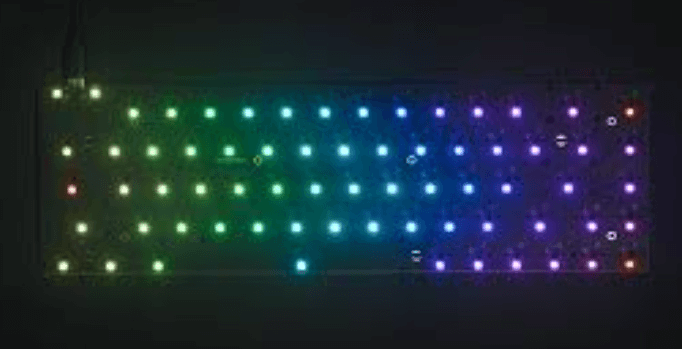
Transitioning from component selection to layout design, the placement of RGB LEDs on the PCB is critical.
Strategic positioning can enhance the visual effect and ensure uniform illumination. It is advisable to place the LEDs in a manner that minimizes shadowing and maximizes light distribution. Additionally, thermal management must be considered, as RGB LEDs can generate significant heat. Incorporating thermal vias and heat sinks can help dissipate heat and maintain the longevity of the LEDs.
The routing of traces is another vital aspect of PCB design for RGB LED integration.
Careful routing ensures that signals are transmitted without interference and that power is distributed evenly. It is important to keep the traces for the RGB channels as short and direct as possible to reduce resistance and potential signal degradation. Moreover, using wider traces for power lines can help manage current flow and prevent overheating.
Incorporating control mechanisms is also a key consideration.
Microcontrollers or dedicated RGB LED controllers are often used to manage the color and brightness of the LEDs. These controllers must be programmed to handle the specific requirements of the application, such as color transitions, patterns, and synchronization with other system components. Ensuring that the firmware is optimized for efficient control can significantly enhance the performance of the RGB LEDs.
Furthermore, the choice of materials for the PCB can impact the overall design.
High-quality substrates with good thermal and electrical properties are recommended to support the performance of RGB LEDs. Additionally, surface finish options such as HASL (Hot Air Solder Leveling) or ENIG (Electroless Nickel Immersion Gold) can affect solderability and longevity of the PCB.
Testing and validation are crucial steps in the design process.
Prototyping allows designers to identify and rectify any issues before mass production. It is essential to test the PCB under various conditions to ensure that the RGB LEDs perform as expected. This includes checking for color consistency, brightness levels, and thermal performance.
In conclusion, designing PCBs for RGB LED integration involves a comprehensive approach that encompasses component selection, layout design, trace routing, control mechanisms, material choice, and thorough testing. By paying attention to these details, designers can create PCBs that not only meet functional requirements but also deliver visually stunning results. The integration of RGB LEDs into PCBs opens up a myriad of possibilities for innovative and dynamic lighting solutions across various industries.
Optimizing Power Management in RGB PCBs
Optimizing power management in RGB PCBs is a critical aspect of modern electronic design, particularly as the demand for visually appealing and energy-efficient devices continues to grow. The integration of RGB (Red, Green, Blue) lighting into printed circuit boards (PCBs) has become increasingly popular in various applications, from consumer electronics to industrial equipment. However, the addition of RGB components introduces new challenges in power management that must be addressed to ensure optimal performance and longevity of the device.
One of the primary considerations in optimizing power management for RGB PCBs is the selection of appropriate power supply components.
The power supply must be capable of delivering stable and sufficient current to the RGB LEDs, which can draw significant power, especially when all colors are illuminated simultaneously. Designers often opt for switching regulators over linear regulators due to their higher efficiency, which is crucial in minimizing heat generation and conserving energy. Additionally, the power supply should have low ripple and noise characteristics to prevent interference with the RGB LEDs and other sensitive components on the PCB.
Another important factor is the implementation of effective current control mechanisms.
RGB LEDs require precise current regulation to maintain consistent brightness and color accuracy. This can be achieved through the use of constant current drivers, which ensure that each LED receives a steady current regardless of variations in supply voltage. Pulse-width modulation (PWM) is a commonly used technique for controlling the brightness of RGB LEDs. By adjusting the duty cycle of the PWM signal, designers can fine-tune the intensity of each color channel, thereby achieving the desired color mixing and effects.
Thermal management is also a critical aspect of power optimization in RGB PCBs.
The high power consumption of RGB LEDs can lead to significant heat generation, which, if not properly managed, can degrade the performance and lifespan of the LEDs and other components. Effective thermal management strategies include the use of heat sinks, thermal vias, and proper PCB layout techniques to dissipate heat away from critical areas. Additionally, selecting LEDs with higher thermal efficiency and lower forward voltage can help reduce heat generation.
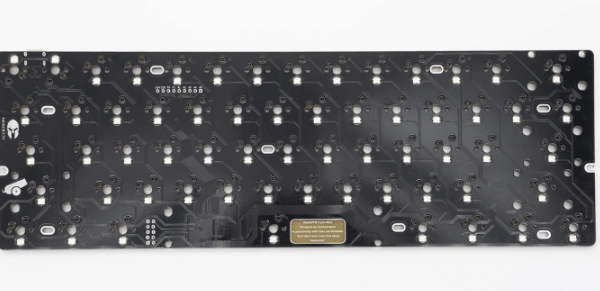
The layout of the PCB itself plays a significant role in power management.
Proper placement of components, adequate trace width, and minimizing the length of high-current paths are essential to reduce power losses and improve overall efficiency. Ground planes and power planes should be carefully designed to provide low-impedance paths for current flow, which helps in reducing voltage drops and electromagnetic interference (EMI). Furthermore, decoupling capacitors should be strategically placed near the RGB LEDs and other critical components to filter out noise and stabilize the power supply.
In addition to hardware considerations, software optimization can also contribute to efficient power management in RGB PCBs.
Implementing intelligent control algorithms that dynamically adjust the brightness and color of the RGB LEDs based on ambient light conditions or user preferences can significantly reduce power consumption. For instance, reducing the brightness of the LEDs in low-light environments or when the device is in standby mode can conserve energy without compromising the visual experience.
In conclusion, optimizing power management in RGB PCBs requires a holistic approach that encompasses careful selection of power supply components, effective current control, robust thermal management, strategic PCB layout, and intelligent software control. By addressing these factors, designers can create RGB-enabled devices that are not only visually stunning but also energy-efficient and reliable. As technology continues to advance, the importance of power optimization in RGB PCBs will only grow, making it a key area of focus for electronic design engineers.
Advanced Soldering Techniques for RGB PCBs
Printed Circuit Boards (PCBs) with integrated RGB lighting have become increasingly popular in various applications, from gaming peripherals to advanced industrial equipment. The vibrant and customizable lighting effects provided by RGB LEDs can significantly enhance the aesthetic appeal and functionality of electronic devices. However, the process of soldering RGB components onto PCBs requires a high level of precision and expertise. Advanced soldering techniques are essential to ensure the reliability and performance of these intricate assemblies.
To begin with, it is crucial to understand the specific requirements of RGB PCBs.
These boards often feature densely packed components and intricate circuitry, necessitating meticulous attention to detail during the soldering process. One of the primary considerations is the selection of appropriate soldering tools and materials. High-quality soldering irons with adjustable temperature controls are indispensable, as they allow for precise temperature management, which is critical when working with sensitive RGB LEDs. Additionally, using lead-free solder can help meet environmental regulations and reduce health risks associated with lead exposure.
Transitioning to the actual soldering process, it is essential to prepare the PCB and components thoroughly.
Cleaning the PCB surface to remove any contaminants, such as dust or oils, is a fundamental step. This can be achieved using isopropyl alcohol and a lint-free cloth. Ensuring that the RGB LEDs and other components are free from oxidation is equally important, as this can affect the quality of the solder joints. Pre-tinning the soldering iron tip and the component leads can facilitate better solder flow and adhesion.
When soldering RGB LEDs, it is vital to pay attention to their polarity.
Incorrectly oriented LEDs will not function correctly and can potentially damage the entire circuit. Most RGB LEDs have a common anode or cathode, and the correct orientation must be verified before soldering. Using a magnifying glass or microscope can aid in accurately positioning the tiny components on the PCB pads.
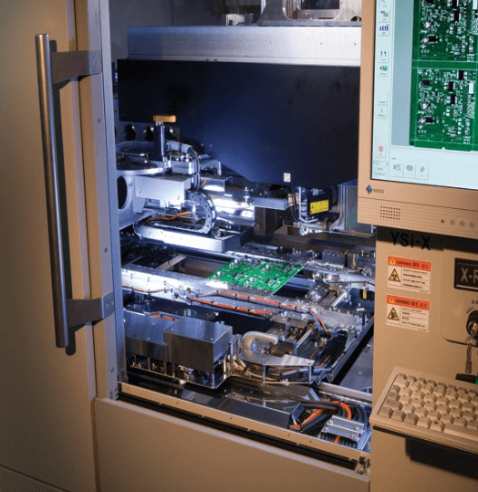
Another advanced technique involves the use of solder paste and a reflow oven.
Solder paste, a mixture of powdered solder and flux, can be precisely applied to the PCB pads using a stencil. The components are then placed onto the paste, and the entire assembly is heated in a reflow oven. The controlled heating process melts the solder paste, creating strong and reliable solder joints. This method is particularly advantageous for soldering multiple RGB LEDs simultaneously, ensuring uniformity and reducing the risk of thermal damage.
In addition to reflow soldering, hot air rework stations can be employed for soldering and desoldering RGB components.
These stations provide a controlled stream of hot air, allowing for precise temperature application. This technique is especially useful for reworking or replacing individual RGB LEDs without affecting adjacent components. However, it requires a steady hand and experience to avoid overheating and damaging the delicate LEDs.
Furthermore, inspecting the solder joints is a critical step in the process.
Poorly formed joints can lead to intermittent connections or complete circuit failure. Visual inspection under magnification can reveal common issues such as cold joints, solder bridges, or insufficient solder coverage. Automated optical inspection (AOI) systems can also be utilized for high-volume production, providing consistent and accurate assessment of solder quality.
In conclusion, advanced soldering techniques are indispensable for assembling RGB PCBs with precision and reliability. From selecting the right tools and materials to employing sophisticated methods like reflow soldering and hot air rework, each step requires careful consideration and expertise. By adhering to these practices, one can ensure the optimal performance and longevity of RGB-enhanced electronic devices, meeting the high standards demanded by modern applications.
Troubleshooting Common Issues in RGB PCB Projects
When working on RGB PCB projects, encountering issues is not uncommon, and troubleshooting these problems can be a meticulous process. Understanding the common issues and their potential solutions is crucial for ensuring the functionality and longevity of your RGB PCB.
One of the most frequent problems is the incorrect placement of components.
Ensuring that each component is correctly oriented and securely soldered is fundamental. Misplaced or poorly soldered components can lead to short circuits or open circuits, which can prevent the RGB LEDs from functioning correctly. Therefore, double-checking the placement and soldering of each component is a necessary step in troubleshooting.
Another prevalent issue is related to power supply inconsistencies.
RGB LEDs require a stable and adequate power supply to function optimally. Insufficient power can cause the LEDs to dim or flicker, while excessive power can damage the LEDs or other components on the PCB. It is essential to verify that the power supply meets the specifications required by the RGB LEDs and the PCB design. Using a multimeter to check the voltage and current levels can help identify any discrepancies in the power supply.
Signal integrity is also a critical factor in RGB PCB projects.
Poor signal integrity can result in erratic behavior of the RGB LEDs, such as incorrect colors or patterns. This issue often arises from improper routing of signal traces or inadequate grounding. Ensuring that signal traces are kept short and direct, and that there is a solid ground plane, can significantly improve signal integrity. Additionally, using decoupling capacitors near the power pins of the RGB LEDs can help filter out noise and stabilize the signals.
Software-related issues can also pose challenges in RGB PCB projects.
Incorrect or buggy firmware can lead to unexpected behavior of the RGB LEDs. It is important to thoroughly test the firmware in a controlled environment before deploying it to the actual PCB. Debugging tools and techniques, such as using a logic analyzer or an oscilloscope, can be invaluable in identifying and resolving software-related issues. Ensuring that the firmware is compatible with the hardware and that it correctly implements the desired functionality is crucial for the success of the project.
Thermal management is another aspect that should not be overlooked.
RGB LEDs can generate significant heat, and inadequate thermal management can lead to overheating and potential failure of the components. Implementing proper heat dissipation techniques, such as using heat sinks or thermal vias, can help manage the heat generated by the RGB LEDs. Monitoring the temperature of the PCB during operation can also provide insights into potential thermal issues.
Lastly, environmental factors can impact the performance of RGB PCBs.
Humidity, dust, and other contaminants can affect the electrical connections and the overall functionality of the PCB. Ensuring that the PCB is properly sealed and protected from environmental factors can help maintain its performance over time. Regular cleaning and maintenance can also prevent the buildup of contaminants that could interfere with the operation of the RGB LEDs.
In conclusion, troubleshooting common issues in RGB PCB projects requires a systematic approach that considers various factors, including component placement, power supply, signal integrity, software, thermal management, and environmental conditions. By addressing these potential issues methodically, one can enhance the reliability and performance of RGB PCB projects, ensuring that they meet the desired specifications and function as intended