Pcb prototype printing
Essential Steps For Successful PCB Prototype Printing
Printed Circuit Board (PCB) prototype printing is a critical phase in the development of electronic devices, serving as a preliminary model to test and validate the design before mass production. To ensure a successful PCB prototype, several essential steps must be meticulously followed, each contributing to the overall functionality and reliability of the final product.
The process begins with a comprehensive design phase, where engineers utilize specialized software to create a detailed schematic of the circuit.
This schematic serves as a blueprint, outlining the electrical connections and components required for the PCB. It is imperative to conduct thorough simulations and analyses at this stage to identify and rectify any potential issues. By doing so, designers can prevent costly errors and ensure that the prototype will function as intended.
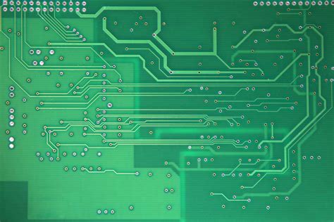
Once the schematic is finalized, the next step involves translating the design into a layout.
This layout specifies the physical placement of components and the routing of electrical traces on the PCB. Precision is crucial here, as even minor deviations can lead to signal integrity problems or component interference. Advanced software tools assist in optimizing the layout, taking into account factors such as trace width, spacing, and layer stack-up. Additionally, designers must adhere to industry standards and guidelines to ensure compatibility and manufacturability.
Following the layout design, the focus shifts to the fabrication of the PCB.
This involves transferring the layout onto a physical substrate, typically made of fiberglass-reinforced epoxy laminate. The process begins with the creation of a photomask, which is used to etch the copper layers on the substrate. Chemical etching removes unwanted copper, leaving behind the desired circuit pattern. It is essential to maintain a controlled environment during this process to prevent contamination and ensure precision.
After etching, the PCB undergoes a series of drilling and plating steps.
Holes are drilled to accommodate component leads and vias, which are plated with copper to establish electrical connections between different layers of the board. The accuracy of these steps is paramount, as misaligned holes or inadequate plating can compromise the functionality of the prototype. Advanced drilling machines and plating techniques are employed to achieve the required precision.
Once the PCB is fabricated, it proceeds to the assembly phase, where components are mounted onto the board.
This can be done using surface-mount technology (SMT) or through-hole technology, depending on the design requirements. Automated pick-and-place machines are commonly used to position components accurately, followed by soldering to secure them in place. Quality control measures, such as visual inspection and automated optical inspection (AOI), are implemented to detect any assembly defects.
The final step in the PCB prototype printing process is testing and validation.
This involves subjecting the prototype to a series of electrical tests to verify its performance and functionality. Engineers use specialized equipment to measure parameters such as signal integrity, power consumption, and thermal performance. Any discrepancies or failures identified during testing must be addressed through iterative design modifications and re-testing.
In conclusion, successful PCB prototype printing requires a methodical approach, encompassing design, layout, fabrication, assembly, and testing. Each step plays a vital role in ensuring the prototype meets the desired specifications and functions reliably. By adhering to best practices and leveraging advanced tools and technologies, engineers can achieve high-quality PCB prototypes that pave the way for successful product development and commercialization.
Top Tools And Software For PCB Prototype Design
Printed Circuit Board (PCB) prototype design is a critical phase in the development of electronic devices, serving as a bridge between conceptualization and mass production. To ensure the success of this phase, engineers and designers rely on a variety of tools and software that streamline the design process, enhance accuracy, and facilitate testing. Among the top tools and software for PCB prototype design, several stand out due to their comprehensive features, user-friendly interfaces, and robust support systems.
One of the most widely used tools in PCB prototype design is Altium Designer.
Known for its powerful schematic capture and PCB layout capabilities, Altium Designer offers an integrated environment that allows for seamless transition from design to prototype. Its advanced routing tools, real-time 3D visualization, and extensive component libraries make it a preferred choice for both novice and experienced designers. Additionally, Altium Designer’s collaboration features enable multiple team members to work on a project simultaneously, ensuring that design iterations are efficiently managed.
Another prominent tool in the realm of PCB prototype design is Eagle, developed by Autodesk.
Eagle is renowned for its ease of use and affordability, making it accessible to hobbyists and small businesses. Despite its simplicity, Eagle does not compromise on functionality. It provides a comprehensive suite of tools for schematic capture, PCB layout, and auto-routing. Furthermore, Eagle’s integration with Autodesk’s Fusion 360 allows for a seamless transition from electronic design to mechanical design, facilitating the creation of complex electromechanical systems.
KiCad is another noteworthy mention in the list of top tools for PCB prototype design.
As an open-source software suite, KiCad offers a cost-effective solution without sacrificing quality. It includes a range of features such as schematic capture, PCB layout, and a 3D viewer. KiCad’s modular design allows users to customize their workflow according to their specific needs. Moreover, its active community of users and developers ensures continuous improvement and support, making it a reliable choice for both professional and amateur designers.
In addition to these tools, DipTrace is also highly regarded in the PCB design community.
DipTrace offers a user-friendly interface combined with powerful features such as hierarchical schematic capture, advanced routing options, and a comprehensive component library. Its 3D preview and export capabilities allow designers to visualize their prototypes in a realistic manner, aiding in the identification of potential issues before physical production. DipTrace’s support for various file formats also ensures compatibility with other design tools and manufacturing processes.
While these tools provide the necessary features for PCB prototype design, the importance of simulation software cannot be overlooked.
Tools like LTSpice and PSpice are essential for simulating electronic circuits and verifying their functionality before committing to a physical prototype. These simulation tools help identify potential issues such as signal integrity problems, thermal management concerns, and power distribution challenges, thereby reducing the risk of costly errors during the prototyping phase.
In conclusion, the selection of the right tools and software is paramount to the success of PCB prototype design. Altium Designer, Eagle, KiCad, and DipTrace each offer unique advantages that cater to different needs and preferences. Complementing these design tools with simulation software like LTSpice and PSpice further enhances the reliability and performance of the final prototype. By leveraging these top tools and software, designers can ensure a smooth transition from concept to prototype, ultimately paving the way for successful product development.
Common Mistakes To Avoid In PCB Prototype Printing
In the realm of electronics, PCB prototype printing is a critical step in the development of new devices. However, the process is fraught with potential pitfalls that can lead to costly delays and suboptimal performance. Understanding and avoiding common mistakes can significantly enhance the efficiency and success of your PCB prototyping endeavors.
One prevalent mistake in PCB prototype printing is inadequate design planning.
Often, designers rush into the printing phase without thoroughly vetting their schematics and layouts. This oversight can result in design flaws that are only discovered after the prototype is printed, necessitating costly revisions. To mitigate this risk, it is essential to conduct a comprehensive design review, including simulations and peer evaluations, before proceeding to the printing stage.
Another frequent error is the improper selection of materials.
The choice of substrate, copper thickness, and solder mask can profoundly impact the performance and durability of the PCB. For instance, using a substrate that cannot withstand the operational environment of the final product can lead to premature failure. Therefore, it is crucial to select materials that align with the specific requirements of your application, considering factors such as thermal conductivity, electrical insulation, and mechanical strength.
Transitioning to the layout phase, component placement is a critical aspect that often goes awry.
Poorly placed components can lead to signal integrity issues, electromagnetic interference, and difficulties in assembly. To avoid these problems, it is advisable to follow best practices for component placement, such as keeping high-speed signal paths short, placing decoupling capacitors close to power pins, and ensuring adequate spacing between components to facilitate heat dissipation and manufacturability.
Furthermore, neglecting design for manufacturability (DFM) guidelines is a common mistake that can complicate the production process.
DFM considerations include ensuring that the PCB layout is compatible with standard manufacturing processes and equipment. For example, trace widths and spacings should adhere to the capabilities of the chosen fabrication house, and vias should be appropriately sized to avoid issues during drilling and plating. By incorporating DFM principles early in the design process, you can reduce the likelihood of manufacturing defects and improve yield rates.
In addition to design and layout issues, errors in the generation of Gerber files can also derail PCB prototype printing.
Gerber files are the standard format for conveying PCB design information to manufacturers, and any inaccuracies in these files can lead to incorrect fabrication. Common mistakes include missing or misaligned layers, incorrect drill files, and improper file naming conventions. To prevent such issues, it is essential to meticulously review and verify all Gerber files before submission, ensuring that they accurately reflect the intended design.
Lastly, insufficient testing and validation of the prototype can result in undetected flaws that manifest in the final product.
It is imperative to conduct thorough testing of the prototype, including functional tests, signal integrity analysis, and environmental stress tests. This rigorous validation process helps identify and rectify any issues before moving to mass production, thereby enhancing the reliability and performance of the final product.
In conclusion, PCB prototype printing is a complex process that demands careful attention to detail and adherence to best practices. By avoiding common mistakes such as inadequate design planning, improper material selection, poor component placement, neglecting DFM guidelines, errors in Gerber file generation, and insufficient testing, you can streamline the prototyping process and achieve superior results. Through diligent planning and execution, you can ensure that your PCB prototypes meet the highest standards of quality and performance.
Innovations And Trends In PCB Prototype Technology
The field of PCB prototype technology has witnessed significant innovations and trends in recent years, driven by the relentless pursuit of efficiency, precision, and cost-effectiveness. As the demand for more complex and compact electronic devices grows, the need for advanced PCB prototypes has become paramount. One of the most notable innovations in this domain is the advent of 3D printing technology, which has revolutionized the way PCB prototypes are designed and manufactured. By enabling rapid prototyping and iterative testing, 3D printing has significantly reduced the time and cost associated with traditional PCB manufacturing processes.
In addition to 3D printing, the integration of advanced materials has also played a crucial role in enhancing PCB prototype technology.
High-performance materials such as flexible substrates, conductive inks, and advanced laminates have enabled the development of more durable and versatile PCBs. These materials not only improve the electrical performance of the prototypes but also allow for greater design flexibility, making it possible to create PCBs with complex geometries and intricate patterns.
Another significant trend in PCB prototype technology is the increasing use of automation and artificial intelligence (AI) in the design and manufacturing processes.
Automation has streamlined the production of PCB prototypes by reducing human error and increasing precision. AI, on the other hand, has facilitated the optimization of PCB designs by analyzing vast amounts of data and identifying potential issues before they arise. This has led to the creation of more reliable and efficient PCB prototypes, ultimately improving the overall quality of electronic devices.
Moreover, the rise of Internet of Things (IoT) and wearable technology has further fueled the demand for innovative PCB prototypes.
These applications require PCBs that are not only compact and lightweight but also capable of withstanding harsh environmental conditions. To meet these requirements, researchers and manufacturers have been exploring new techniques such as embedding components within the PCB substrate and using advanced thermal management solutions. These innovations have enabled the development of PCBs that are both highly functional and resilient, catering to the specific needs of IoT and wearable devices.
Furthermore, the trend towards miniaturization has also had a profound impact on PCB prototype technology.
As electronic devices continue to shrink in size, the need for smaller and more densely packed PCBs has become increasingly important. This has led to the adoption of advanced manufacturing techniques such as laser direct imaging (LDI) and microvia technology, which allow for the creation of high-density interconnects (HDI) and multi-layer PCBs. These techniques have not only improved the performance of PCB prototypes but also enabled the development of more compact and efficient electronic devices.
In conclusion, the innovations and trends in PCB prototype technology have significantly transformed the landscape of electronic device manufacturing. The advent of 3D printing, the integration of advanced materials, the use of automation and AI, the rise of IoT and wearable technology, and the trend towards miniaturization have all contributed to the development of more efficient, reliable, and versatile PCB prototypes. As the demand for advanced electronic devices continues to grow, it is expected that these innovations and trends will further evolve, paving the way for even more groundbreaking advancements in PCB prototype technology.