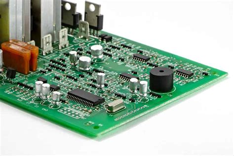
Board layout design
Optimizing Signal Integrity in PCB Design
In the realm of printed circuit board (PCB) design, optimizing signal integrity is a critical aspect that demands meticulous attention. Signal integrity refers to the quality and reliability of electrical signals as they travel through the PCB. Poor signal integrity can lead to data errors, electromagnetic interference, and overall system malfunction, which underscores the importance of effective board layout design. To achieve optimal signal integrity, designers must consider several key factors, including trace routing, impedance control, and component placement.
Firstly, trace routing plays a pivotal role in maintaining signal integrity.
The path that electrical signals take across the PCB can significantly impact their quality. Designers should aim to minimize trace lengths, as longer traces can introduce unwanted inductance and capacitance, leading to signal degradation. Additionally, it is advisable to avoid sharp angles in trace routing, as these can cause reflections and impedance discontinuities. Instead, using smooth, gradual curves can help maintain consistent impedance and reduce signal loss. Furthermore, differential pairs, which are pairs of traces carrying complementary signals, should be routed closely together to minimize electromagnetic interference and maintain signal integrity.
In conjunction with trace routing, impedance control is another crucial aspect of board layout design.
Impedance refers to the resistance that a circuit presents to the flow of alternating current. For high-speed digital signals, maintaining a consistent impedance is essential to prevent signal reflections and ensure signal integrity. Designers can achieve this by carefully selecting the width and spacing of traces, as well as the dielectric material and thickness of the PCB. Controlled impedance traces are often used in high-speed designs to match the impedance of the transmission line with that of the connected components, thereby minimizing reflections and signal loss.
Moreover, component placement is integral to optimizing signal integrity.
Strategic placement of components can reduce the length of critical signal paths and minimize the potential for interference. Placing components that interact frequently close to each other can help reduce trace lengths and improve signal quality. Additionally, separating analog and digital components can prevent crosstalk, which is the unwanted transfer of signals between adjacent traces. By isolating these components, designers can mitigate the risk of interference and maintain the integrity of both analog and digital signals.
Transitioning to another important consideration, the use of ground planes is essential in enhancing signal integrity.
Ground planes provide a low-impedance path for return currents, which helps reduce electromagnetic interference and improve signal quality. By placing a continuous ground plane beneath signal traces, designers can create a controlled impedance environment that supports high-speed signal transmission. Furthermore, ground planes can act as a shield against external electromagnetic interference, further safeguarding signal integrity.
In addition to these design strategies, employing simulation tools can be invaluable in optimizing signal integrity.
Simulation software allows designers to model and analyze the behavior of signals within the PCB, identifying potential issues before physical prototyping. By simulating different scenarios, designers can make informed decisions about trace routing, impedance control, and component placement, ultimately leading to a more robust and reliable PCB design.
In conclusion, optimizing signal integrity in PCB design is a multifaceted process that requires careful consideration of trace routing, impedance control, component placement, and the use of ground planes. By addressing these factors and utilizing simulation tools, designers can enhance the performance and reliability of their PCBs, ensuring that electrical signals are transmitted with minimal degradation and interference. As technology continues to advance, the importance of signal integrity in PCB design will only grow, making it an essential focus for designers striving to create high-performance electronic systems.

Best Practices for Component Placement
In the realm of electronic design, board layout design is a critical phase that significantly influences the performance, reliability, and manufacturability of a printed circuit board (PCB). Among the various aspects of board layout design, component placement stands out as a fundamental step that requires meticulous attention to detail. Proper component placement not only ensures optimal functionality but also facilitates efficient routing, thermal management, and signal integrity. Therefore, understanding the best practices for component placement is essential for engineers and designers aiming to create high-quality PCBs.
To begin with, it is crucial to consider the functional grouping of components.
Grouping components based on their function can simplify the routing process and enhance the overall performance of the board. For instance, placing all power-related components in one area can help in minimizing the power loop area, thereby reducing electromagnetic interference (EMI). Similarly, grouping analog and digital components separately can prevent noise interference between sensitive analog signals and high-speed digital signals. This strategic organization not only aids in maintaining signal integrity but also streamlines the debugging and testing processes.
In addition to functional grouping, attention must be paid to the orientation of components.
Consistent orientation of similar components can significantly ease the assembly process, reducing the likelihood of errors during manufacturing. For example, aligning all polarized components, such as diodes and capacitors, in the same direction can facilitate automated assembly and inspection. Moreover, ensuring that components are oriented to minimize trace lengths can enhance signal integrity and reduce potential issues related to signal delay and distortion.
Another critical consideration in component placement is thermal management.
Components that generate significant heat, such as power transistors and voltage regulators, should be placed in areas that allow for efficient heat dissipation. This can be achieved by positioning these components near the edges of the board or in proximity to heat sinks and thermal vias. Additionally, it is advisable to avoid placing heat-sensitive components, such as integrated circuits and sensors, near heat-generating elements to prevent thermal damage and ensure reliable operation.
Furthermore, designers should be mindful of the mechanical constraints and physical dimensions of the board.
Ensuring that components do not interfere with mounting holes, connectors, or other mechanical features is vital for the successful integration of the PCB into its final application. It is also important to consider the height and footprint of components to avoid conflicts during enclosure assembly and to maintain a compact and efficient board layout.
Transitioning to the aspect of manufacturability, it is essential to adhere to design for manufacturability (DFM) guidelines during component placement.
This includes maintaining adequate spacing between components to accommodate soldering processes and ensuring that components are accessible for testing and rework. By considering these factors, designers can minimize production costs and reduce the risk of defects during manufacturing.
In conclusion, effective component placement is a cornerstone of successful board layout design. By adhering to best practices such as functional grouping, consistent orientation, thermal management, and consideration of mechanical constraints, designers can create PCBs that are not only functional and reliable but also cost-effective and manufacturable. As technology continues to advance, the importance of meticulous component placement in achieving high-performance electronic designs cannot be overstated.
Thermal Management Strategies in Board Layout
In the realm of electronic design, board layout plays a pivotal role in ensuring the optimal performance and longevity of electronic devices. One of the critical aspects of board layout design is thermal management, which is essential for maintaining the reliability and efficiency of electronic components. As electronic devices become increasingly compact and powerful, the challenge of managing heat dissipation effectively has grown more complex. Therefore, understanding and implementing effective thermal management strategies is crucial for engineers and designers.
To begin with, the importance of thermal management in board layout design cannot be overstated.
Excessive heat can lead to component failure, reduced performance, and shortened lifespan of electronic devices. Consequently, designers must consider thermal management from the initial stages of board layout design. By doing so, they can ensure that heat is efficiently dissipated, thereby maintaining the integrity and functionality of the device.
One fundamental strategy in thermal management is the strategic placement of components.
By positioning heat-generating components, such as processors and power supplies, away from heat-sensitive components, designers can minimize the risk of thermal interference. Additionally, placing these components near the edges of the board can facilitate better heat dissipation, as it allows for more effective airflow around the components. This approach not only aids in heat management but also contributes to the overall efficiency of the device.
Moreover, the use of thermal vias is another effective strategy in board layout design.
Thermal vias are small holes that connect different layers of a printed circuit board (PCB), allowing heat to be transferred from the top layer to the bottom layer or to an internal layer. By incorporating thermal vias, designers can enhance the thermal conductivity of the board, thereby improving heat dissipation. This technique is particularly useful in multilayer boards, where heat can be trapped between layers, leading to potential overheating issues.
In addition to component placement and thermal vias, the selection of appropriate materials is crucial for effective thermal management.
Materials with high thermal conductivity, such as copper, are often used in PCBs to facilitate heat dissipation. Copper traces and planes can be strategically designed to spread heat across the board, reducing hotspots and ensuring a more uniform temperature distribution. Furthermore, the use of thermal interface materials (TIMs) can enhance the thermal connection between components and heat sinks, further improving heat dissipation.
Another vital aspect of thermal management is the implementation of heat sinks and cooling systems.
Heat sinks are passive devices that absorb and dissipate heat from electronic components. By increasing the surface area available for heat dissipation, heat sinks can significantly reduce the temperature of components. In more demanding applications, active cooling systems, such as fans or liquid cooling, may be employed to provide additional thermal management. These systems can be integrated into the board layout design to ensure that heat is effectively managed, even under high-performance conditions.
In conclusion, thermal management is a critical consideration in board layout design, with significant implications for the performance and reliability of electronic devices. By employing strategies such as strategic component placement, the use of thermal vias, selecting appropriate materials, and integrating heat sinks and cooling systems, designers can effectively manage heat dissipation. As electronic devices continue to evolve, the importance of robust thermal management strategies will only increase, underscoring the need for ongoing innovation and attention in this area.
Designing for Manufacturability: Tips and Tricks
Designing for manufacturability is a critical aspect of board layout design, ensuring that a printed circuit board (PCB) can be produced efficiently and cost-effectively while maintaining high quality. As the demand for more complex and compact electronic devices grows, the importance of a well-thought-out board layout cannot be overstated. To achieve this, designers must consider several factors that influence the manufacturability of a PCB, starting with the selection of materials and components.
Choosing the right materials is fundamental to the manufacturability of a PCB.
The substrate material, typically FR-4, must be compatible with the intended application and environmental conditions. Additionally, the selection of components should take into account their availability, cost, and compatibility with automated assembly processes. By prioritizing commonly used components, designers can reduce lead times and minimize the risk of supply chain disruptions.
Transitioning from material selection to layout considerations, it is essential to focus on component placement and routing.
Proper component placement not only affects the electrical performance of the board but also its manufacturability. Components should be arranged to minimize trace lengths and avoid crossing signals, which can complicate the routing process. Furthermore, placing components on a grid can facilitate automated assembly and inspection, reducing the likelihood of errors during production.
Routing, another critical aspect of board layout design, requires careful planning to ensure signal integrity and manufacturability.
Designers should aim to use uniform trace widths and clearances, adhering to the design rules specified by the manufacturer. This consistency helps prevent issues such as impedance mismatches and signal reflections, which can degrade the performance of the final product. Additionally, maintaining adequate spacing between traces and components is crucial to avoid short circuits and ensure reliable operation.
As we delve deeper into the intricacies of board layout design, it is important to consider the role of design for testability (DFT).
Incorporating test points and access nodes into the layout can significantly enhance the ability to test and diagnose the PCB during production. This foresight can lead to early detection of defects, reducing the need for costly rework and improving overall product quality. Moreover, designing with testability in mind can streamline the transition from prototyping to mass production, as it allows for more efficient testing processes.
Thermal management is another vital consideration in designing for manufacturability.
As electronic devices become more powerful, managing heat dissipation becomes increasingly important. Designers should incorporate thermal vias, heat sinks, and copper pours to effectively manage heat distribution across the board. By addressing thermal issues early in the design process, manufacturers can avoid potential failures and extend the lifespan of the product.
In conclusion, designing for manufacturability in board layout design requires a comprehensive approach that considers material selection, component placement, routing, testability, and thermal management. By integrating these elements into the design process, engineers can create PCBs that are not only functional and reliable but also cost-effective to produce. As technology continues to evolve, staying informed about best practices and emerging trends in board layout design will be essential for maintaining a competitive edge in the electronics industry. Through careful planning and attention to detail, designers can ensure that their products meet the demands of both manufacturers and end-users alike.