Metal core pcb design guide
Understanding The Basics Of Metal Core PCB Design
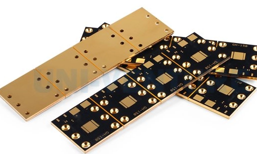
Metal Core Printed Circuit Boards (MCPCBs) have emerged as a pivotal innovation in the realm of electronics, particularly in applications demanding efficient heat dissipation. Understanding the basics of metal core PCB design is essential for engineers and designers aiming to leverage their unique properties. At the heart of MCPCBs is a metal substrate, typically aluminum or copper, which serves as the core material.
This metal core is sandwiched between layers of dielectric material and copper circuitry, providing a robust platform for electronic components.
The primary advantage of using a metal core is its superior thermal conductivity compared to traditional FR-4 boards, making it ideal for high-power applications such as LED lighting, power supplies, and automotive electronics.
To begin with, the choice of metal core material is crucial. Aluminum is often preferred due to its lightweight nature and cost-effectiveness, while copper offers higher thermal conductivity but at a greater expense.
The selection depends on the specific thermal management requirements and budget constraints of the project. Once the core material is chosen, the next step involves designing the dielectric layer, which electrically insulates the metal core from the copper circuitry. This layer must possess excellent thermal conductivity to facilitate efficient heat transfer from the components to the metal core. Materials such as epoxy resin or ceramic-filled polymers are commonly used for this purpose.
Transitioning to the design of the copper circuitry, it is essential to consider the layout and thickness of the copper traces.
The layout should be optimized to minimize thermal resistance and ensure uniform heat distribution across the board. Thicker copper layers can handle higher current loads, which is beneficial in high-power applications. However, this must be balanced against the increased cost and potential challenges in manufacturing. Additionally, the placement of components on the MCPCB should be strategically planned to enhance thermal performance. Heat-generating components should be positioned close to the metal core to maximize heat dissipation, while sensitive components should be placed further away to avoid thermal interference.
Furthermore, the integration of thermal vias can significantly enhance the thermal management capabilities of MCPCBs.
These vias are strategically placed to create a direct thermal path from the heat source to the metal core, thereby improving heat dissipation. The design and placement of thermal vias require careful consideration to avoid compromising the structural integrity of the board. Moreover, the solder mask and surface finish of the MCPCB play a vital role in its overall performance. The solder mask should be selected to withstand high temperatures, while the surface finish must ensure reliable solderability and corrosion resistance.
In conclusion, understanding the basics of metal core PCB design involves a comprehensive approach that considers material selection, thermal management, and component placement. By carefully balancing these factors, designers can create MCPCBs that offer superior performance in demanding applications. As technology continues to advance, the role of MCPCBs in electronics is expected to grow, driven by the increasing need for efficient thermal management solutions. Therefore, mastering the fundamentals of metal core PCB design is not only beneficial but essential for those involved in the development of cutting-edge electronic devices.
Key Advantages Of Using Metal Core PCBs In Electronics
Metal Core Printed Circuit Boards (PCBs) have emerged as a pivotal innovation in the electronics industry, offering a range of advantages that make them an attractive choice for various applications. These PCBs are distinguished by their metal core, typically composed of aluminum, copper, or a mixture of special alloys, which serves as a thermal management solution. This unique construction provides several key benefits that enhance the performance and reliability of electronic devices.
One of the primary advantages of metal core PCBs is their superior thermal conductivity.
In electronic devices, heat dissipation is a critical factor that can significantly impact performance and longevity. Traditional PCBs, often made from fiberglass or other non-metallic materials, can struggle to efficiently dissipate heat, leading to potential overheating and failure of components. In contrast, the metal core in these PCBs acts as a heat sink, effectively drawing heat away from critical components and distributing it across the board. This capability not only prevents overheating but also allows for higher power densities, enabling the design of more compact and efficient electronic devices.
Moreover, metal core PCBs offer enhanced mechanical stability.
The metal core provides a robust foundation that reduces the risk of warping or bending, which can occur in standard PCBs under thermal stress. This stability is particularly beneficial in applications where the PCB is subjected to harsh environmental conditions or mechanical stress, such as in automotive or industrial electronics. The durability of metal core PCBs ensures that they maintain their structural integrity over time, thereby extending the lifespan of the electronic devices in which they are used.
In addition to thermal and mechanical advantages, metal core PCBs also contribute to improved electrical performance.
The metal core can serve as a ground plane, reducing electromagnetic interference (EMI) and enhancing signal integrity. This is especially important in high-frequency applications where signal clarity is paramount. By minimizing EMI, metal core PCBs help ensure that electronic devices operate reliably and efficiently, even in environments with significant electromagnetic noise.
Furthermore, the use of metal core PCBs can lead to cost savings in the long run.
While the initial cost of manufacturing these PCBs may be higher than that of traditional PCBs, their ability to improve thermal management and reliability can reduce the need for additional cooling solutions and maintenance. This can result in lower overall system costs and a more streamlined design process. Additionally, the extended lifespan and enhanced performance of devices using metal core PCBs can lead to reduced downtime and maintenance expenses, further contributing to cost efficiency.
In conclusion, the adoption of metal core PCBs in electronics offers a multitude of advantages that address some of the most pressing challenges in modern electronic design. Their superior thermal management capabilities, mechanical stability, and improved electrical performance make them an ideal choice for a wide range of applications, from consumer electronics to industrial systems. As the demand for more powerful and compact electronic devices continues to grow, the role of metal core PCBs in meeting these demands is likely to become increasingly significant. By leveraging the unique properties of metal core PCBs, designers and manufacturers can create more reliable, efficient, and cost-effective electronic solutions.
Step-By-Step Guide To Designing A Metal Core PCB
Designing a metal core printed circuit board (MCPCB) involves a series of meticulous steps that ensure optimal performance and reliability, particularly in applications where heat dissipation is critical. The process begins with understanding the unique properties of MCPCBs, which are distinguished by their metal core, typically aluminum or copper, that provides superior thermal conductivity compared to traditional FR-4 boards. This characteristic makes them ideal for high-power applications such as LED lighting, power converters, and automotive electronics.
The first step in designing an MCPCB is to define the requirements of the application.
This involves determining the thermal and electrical performance needs, which will guide the selection of materials and the overall design approach. It is crucial to consider the thermal conductivity of the metal core, as this will directly impact the board’s ability to dissipate heat. Additionally, the thickness of the metal core must be chosen carefully to balance mechanical strength and thermal performance.
Once the requirements are established, the next step is to create a schematic diagram.
This involves mapping out the electrical connections and components that will be placed on the board. During this phase, it is important to consider the placement of heat-generating components and ensure they are positioned to maximize heat dissipation through the metal core. The schematic serves as a blueprint for the subsequent layout design.
Transitioning to the layout design, the focus shifts to arranging the components on the board and routing the electrical connections.
In MCPCB design, special attention must be paid to the thermal management aspects. This includes strategically placing thermal vias, which are conductive pathways that help transfer heat from the surface components to the metal core. The layout should also minimize the length of high-current traces to reduce resistive losses and potential hotspots.
Following the layout design, the next step is to perform thermal simulations.
These simulations are crucial for predicting the thermal performance of the MCPCB under various operating conditions. By using specialized software, designers can model the heat distribution across the board and identify any potential thermal issues. This step allows for adjustments to be made before the physical prototype is created, saving time and resources.
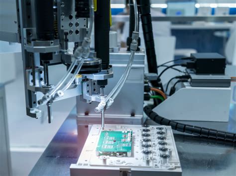
After validating the design through simulations, the prototype fabrication process begins.
This involves selecting a manufacturer with experience in producing MCPCBs, as the process differs from standard PCB fabrication. The metal core must be precisely machined, and the dielectric layer, which electrically isolates the metal core from the circuit layer, must be applied with precision to ensure reliability.
Once the prototype is fabricated, it undergoes rigorous testing to verify its performance against the design specifications.
This includes electrical testing to ensure proper functionality and thermal testing to confirm effective heat dissipation. Any discrepancies identified during testing may necessitate design revisions and further prototyping.
In conclusion, designing a metal core PCB is a complex process that requires careful consideration of thermal management, material selection, and precise fabrication techniques. By following a structured approach, designers can create MCPCBs that meet the demanding requirements of high-power applications, ensuring both performance and reliability. As technology continues to advance, the role of MCPCBs in managing heat in electronic devices will only become more critical, underscoring the importance of mastering this specialized design process.
Common Challenges And Solutions In Metal Core PCB Design
Designing metal core printed circuit boards (PCBs) presents a unique set of challenges that require careful consideration and strategic solutions. As the demand for high-performance electronic devices continues to grow, metal core PCBs have become increasingly popular due to their superior thermal management capabilities. However, the integration of metal cores into PCB design introduces complexities that can impact both the manufacturing process and the performance of the final product.
One of the primary challenges in metal core PCB design is managing thermal expansion.
Unlike traditional PCBs, which are typically made from materials like FR-4, metal core PCBs incorporate a metal layer, often aluminum or copper, to dissipate heat more effectively. This metal layer can expand and contract with temperature changes, potentially leading to mechanical stress and misalignment of components. To address this issue, designers must carefully select materials with compatible coefficients of thermal expansion (CTE) and consider the use of thermal vias and pads to facilitate heat dissipation while minimizing stress.
Another significant challenge is the complexity of the manufacturing process.
The presence of a metal core necessitates specialized fabrication techniques, which can increase production costs and time. For instance, drilling through metal requires more precise equipment and can lead to increased tool wear. To mitigate these challenges, manufacturers often employ advanced drilling techniques, such as laser drilling, which can provide greater accuracy and reduce wear on tools. Additionally, designers can optimize the layout to minimize the number of required drill holes, thereby reducing manufacturing complexity.
Signal integrity is also a critical concern in metal core PCB design.
The metal layer can introduce electromagnetic interference (EMI), which can degrade signal quality and affect the performance of the device. To combat this, designers must implement effective grounding strategies and consider the use of shielding techniques. For example, incorporating ground planes and strategically placing decoupling capacitors can help reduce EMI and improve signal integrity. Furthermore, careful routing of signal traces and maintaining adequate spacing between them can prevent crosstalk and ensure reliable signal transmission.
Moreover, the integration of metal cores can impact the mechanical properties of the PCB, such as flexibility and weight
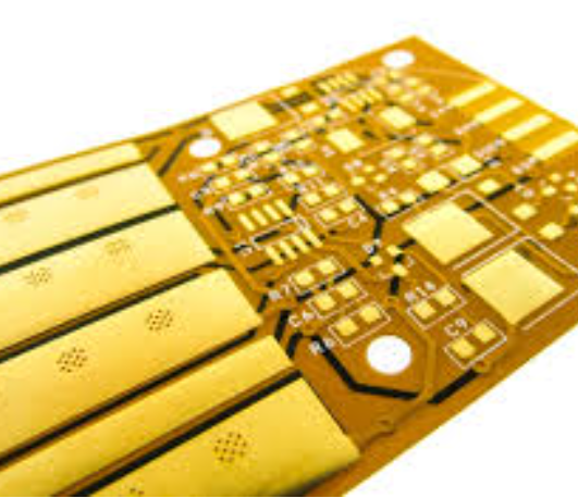
. While the metal core provides enhanced thermal performance, it can also make the PCB more rigid and heavier, which may not be suitable for all applications. Designers must balance these trade-offs by considering the specific requirements of the application and selecting appropriate materials and thicknesses for the metal core. In some cases, hybrid designs that combine metal cores with flexible substrates can offer a viable solution, providing both thermal management and mechanical flexibility.
Finally, cost considerations play a crucial role in metal core PCB design.
The specialized materials and manufacturing processes required for these PCBs can lead to higher production costs compared to traditional PCBs. To address this, designers should focus on optimizing the design for manufacturability, which includes minimizing the number of layers, reducing the complexity of the layout, and selecting cost-effective materials. Collaborating closely with manufacturers during the design phase can also help identify potential cost-saving opportunities and ensure that the design is feasible within budget constraints.
In conclusion, while metal core PCB design presents several challenges, understanding these issues and implementing strategic solutions can lead to successful outcomes.
By carefully managing thermal expansion, optimizing the manufacturing process, ensuring signal integrity, balancing mechanical properties, and considering cost implications, designers can effectively harness the benefits of metal core PCBs for high-performance applications.

