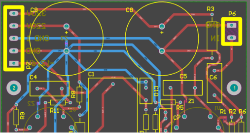
Iphone 7 pcb diagram
Understanding The iPhone 7 PCB Diagram: A Comprehensive Guide
The iPhone 7, a hallmark of Apple’s innovative design, is a marvel of modern engineering, and at the heart of its functionality lies the printed circuit board (PCB). Understanding the iPhone 7 PCB diagram is crucial for those interested in the intricate workings of this device, whether for repair, educational purposes, or sheer curiosity.
The PCB serves as the backbone of the iPhone 7, housing and interconnecting its various components, which include the processor, memory, and other essential electronic parts. By examining the PCB diagram, one can gain insights into how these components are organized and how they communicate with each other to deliver the seamless performance that users have come to expect from Apple products.
To begin with, the iPhone 7 PCB diagram reveals the layout of the A10 Fusion chip, which is the central processing unit responsible for executing instructions and managing tasks.
This chip is a quad-core processor that combines two high-performance cores with two energy-efficient cores, allowing the device to balance power and efficiency. The diagram illustrates how the A10 Fusion chip is connected to other critical components, such as the RAM and storage, enabling swift data processing and retrieval. Furthermore, the PCB diagram highlights the placement of the NAND flash memory, which stores the operating system, applications, and user data. Understanding these connections is vital for anyone looking to repair or modify the device, as it provides a roadmap for navigating the complex circuitry.
In addition to the processor and memory, the iPhone 7 PCB diagram also details the power management integrated circuit (PMIC), which plays a crucial role in regulating the device’s power consumption.
The PMIC ensures that each component receives the appropriate voltage and current, thereby optimizing battery life and preventing damage from power surges. By studying the PCB diagram, one can identify the pathways through which power is distributed across the board, offering insights into the device’s energy management strategies. This knowledge is particularly valuable for technicians who need to diagnose power-related issues or replace faulty components.
Moreover, the iPhone 7 PCB diagram provides a comprehensive view of the device’s connectivity features, including the Wi-Fi, Bluetooth, and cellular network modules.
These components are strategically positioned on the PCB to minimize interference and maximize signal strength, ensuring reliable communication with external devices and networks. The diagram also shows the antenna connections, which are critical for maintaining strong and stable connections. Understanding the layout of these connectivity components can aid in troubleshooting network issues and enhancing the device’s performance.
Transitioning to the audio and visual components, the PCB diagram outlines the placement of the audio codec and the display controller.
The audio codec is responsible for converting digital audio signals into analog signals that can be played through the device’s speakers or headphones. Meanwhile, the display controller manages the rendering of images and videos on the screen, ensuring smooth and vibrant visuals. By examining the PCB diagram, one can appreciate the meticulous design that goes into delivering high-quality audio and visual experiences on the iPhone 7.
In conclusion, the iPhone 7 PCB diagram is an invaluable resource for understanding the inner workings of this sophisticated device. It offers a detailed map of the components and their interconnections, providing insights into the design and functionality of the iPhone 7. Whether for repair, education, or personal interest, studying the PCB diagram can deepen one’s appreciation for the engineering prowess that underpins Apple’s iconic smartphone.
Key Components Of The iPhone 7 PCB Diagram Explained
The iPhone 7, released by Apple in 2016, marked a significant evolution in smartphone technology, not only in terms of user interface and design but also in its internal architecture. At the heart of this architecture lies the printed circuit board (PCB), a complex and meticulously designed component that serves as the backbone for the device’s electronic functions. Understanding the key components of the iPhone 7 PCB diagram provides valuable insights into how this device operates and the technological advancements it embodies.
To begin with, the central processing unit (CPU) is a critical component of the iPhone 7’s PCB.
The A10 Fusion chip, which powers the iPhone 7, is a quad-core processor that significantly enhances the device’s performance and efficiency. This chip integrates two high-performance cores and two high-efficiency cores, allowing the device to balance power and energy consumption effectively. The placement of the A10 Fusion chip on the PCB is strategic, ensuring optimal connectivity with other components and minimizing latency.
Adjacent to the CPU, the memory modules are another vital aspect of the PCB.
The iPhone 7 is equipped with 2GB of LPDDR4 RAM, which facilitates smooth multitasking and quick access to frequently used applications. The RAM is soldered directly onto the PCB, a design choice that enhances the device’s speed and reliability. This integration is crucial for maintaining the seamless user experience that Apple products are known for.
Moreover, the storage component of the iPhone 7’s PCB is worth noting.
The device offers various storage options, ranging from 32GB to 256GB, utilizing NAND flash memory. This type of memory is non-volatile, meaning it retains data even when the device is powered off. The NAND flash memory is also directly soldered onto the PCB, ensuring fast data retrieval and storage capabilities. This integration is essential for supporting the high-resolution photos and videos that users capture with the iPhone 7’s advanced camera system.
In addition to these components, the power management integrated circuit (PMIC) plays a crucial role in the iPhone 7’s PCB.
The PMIC is responsible for regulating the power distribution throughout the device, ensuring that each component receives the appropriate voltage and current. This regulation is vital for maintaining the device’s battery life and preventing overheating, which can lead to hardware damage. The PMIC’s strategic placement on the PCB allows it to efficiently manage power flow, contributing to the overall stability and longevity of the device.
Furthermore, the iPhone 7’s PCB includes various connectivity modules, such as the Wi-Fi and Bluetooth chips.
These components enable the device to connect to wireless networks and other devices seamlessly. The integration of these modules into the PCB is designed to optimize signal strength and reduce interference, ensuring reliable connectivity for users.
Lastly, the audio codec and amplifier are integral parts of the iPhone 7’s PCB.
These components are responsible for processing and enhancing audio signals, delivering the high-quality sound that users expect from an Apple device. The careful placement and integration of these audio components on the PCB contribute to the iPhone 7’s superior audio performance.
In conclusion, the iPhone 7 PCB diagram reveals a sophisticated network of components that work in harmony to deliver a powerful and efficient smartphone experience. From the A10 Fusion chip to the power management system, each element is meticulously designed and strategically placed to optimize performance, connectivity, and user satisfaction. Understanding these key components provides a deeper appreciation for the technological innovation that defines the iPhone 7.

Troubleshooting Common Issues Using The iPhone 7 PCB Diagram
The iPhone 7, a popular model in Apple’s lineup, is known for its sleek design and advanced features. However, like any electronic device, it can encounter issues over time. Understanding the iPhone 7 PCB (Printed Circuit Board) diagram can be instrumental in troubleshooting common problems. The PCB diagram serves as a blueprint of the phone’s internal circuitry, providing a detailed map of the connections and components that make the device function. By examining this diagram, technicians and knowledgeable users can identify potential problem areas and address them effectively.
To begin with, the iPhone 7 PCB diagram is essential for diagnosing power-rel Zated issues.
If the device fails to power on or experiences intermittent shutdowns, the diagram can help pinpoint the power management IC (Integrated Circuit) and related components. By tracing the power flow from the battery to the logic board, one can identify faulty connections or damaged components that may be causing the issue. Furthermore, the diagram can assist in locating the charging circuit, which is crucial when the device does not charge properly. By understanding the layout and connections, technicians can test and replace faulty components, ensuring the device receives the necessary power.
In addition to power issues, the iPhone 7 PCB diagram is invaluable for addressing audio problems.
Users may encounter issues such as no sound, distorted audio, or malfunctioning microphones. The diagram provides a clear view of the audio IC and its connections to the speakers and microphones. By examining these pathways, technicians can identify broken traces or defective components that may be affecting audio performance. Moreover, the diagram can guide the repair process by indicating the precise location of components, making it easier to replace or re-solder them as needed.
Transitioning to connectivity issues, the iPhone 7 PCB diagram is equally beneficial.
Problems with Wi-Fi, Bluetooth, or cellular connectivity can often be traced back to the RF (Radio Frequency) components on the PCB. The diagram outlines the RF pathways and highlights the antennas and related circuits. By following these pathways, technicians can diagnose issues such as weak signals or dropped connections. The diagram also aids in identifying damaged or disconnected antennas, which are common culprits in connectivity problems. By addressing these issues, users can restore reliable communication capabilities to their devices.
Moreover, the iPhone 7 PCB diagram is a valuable tool for resolving display-related issues.
Problems such as a blank screen, flickering, or unresponsive touch can often be linked to the display IC and its connections. The diagram provides a detailed view of the display circuitry, allowing technicians to trace signals and identify potential faults. By examining the connections between the display and the logic board, one can determine if a faulty component or a broken trace is causing the issue. This information is crucial for effective troubleshooting and repair, ensuring the display functions as intended.
In conclusion, the iPhone 7 PCB diagram is an indispensable resource for troubleshooting common issues.
Whether dealing with power, audio, connectivity, or display problems, the diagram provides a comprehensive view of the device’s internal circuitry. By understanding the layout and connections, technicians and knowledgeable users can diagnose and address issues with precision. This not only enhances the repair process but also extends the lifespan of the device, ensuring users can continue to enjoy their iPhone 7 without interruption.
How The iPhone 7 PCB Diagram Enhances Repair Efficiency
The iPhone 7, a hallmark of Apple’s innovative design, continues to be a popular device among users worldwide. One of the critical aspects that contribute to its enduring appeal is the efficiency with which it can be repaired, a factor significantly enhanced by the detailed iPhone 7 PCB (Printed Circuit Board) diagram. Understanding the intricacies of this diagram is essential for technicians and repair professionals, as it provides a comprehensive blueprint of the device’s internal architecture. By examining the PCB diagram, repair specialists can gain insights into the layout and interconnections of various components, thereby streamlining the repair process.
The iPhone 7 PCB diagram serves as a map that outlines the precise location of each component on the circuit board.
This includes the central processing unit (CPU), memory chips, power management ICs, and other critical elements that ensure the device’s functionality. By having access to this detailed schematic, technicians can quickly identify the components that may be causing issues, such as power failures or connectivity problems. Consequently, this reduces the time spent on diagnostics, allowing for faster and more efficient repairs.
Moreover, the PCB diagram aids in understanding the complex network of traces and vias that connect different components.
These connections are crucial for the seamless operation of the iPhone 7, as they facilitate communication between various parts of the device. When a fault occurs, it is often due to a break or short in these connections. The diagram provides a visual representation of these pathways, enabling repair professionals to pinpoint the exact location of faults. This precision not only enhances repair efficiency but also minimizes the risk of further damage during the repair process.
In addition to aiding in fault diagnosis, the iPhone 7 PCB diagram is instrumental in component replacement.
Given the compact and intricate design of modern smartphones, replacing a faulty component can be a daunting task. However, with the help of the PCB diagram, technicians can accurately identify the component that needs replacement and understand how it is integrated into the overall system. This knowledge is crucial for ensuring that the replacement process is carried out correctly, thereby restoring the device to its optimal performance.
Furthermore, the availability of the iPhone 7 PCB diagram fosters a more competitive repair market.
Independent repair shops and technicians can access this information, allowing them to offer high-quality repair services that rival those provided by authorized service centers. This democratization of repair knowledge not only benefits consumers by providing them with more options but also encourages innovation and skill development within the repair industry.
In conclusion, the iPhone 7 PCB diagram is an invaluable tool that significantly enhances repair efficiency. By providing a detailed overview of the device’s internal structure, it enables technicians to diagnose faults accurately, replace components effectively, and ultimately extend the lifespan of the device. As technology continues to evolve, the importance of such diagrams in facilitating efficient and reliable repairs cannot be overstated. They represent a crucial intersection of design and functionality, ensuring that devices like the iPhone 7 remain serviceable and sustainable in the long term.


