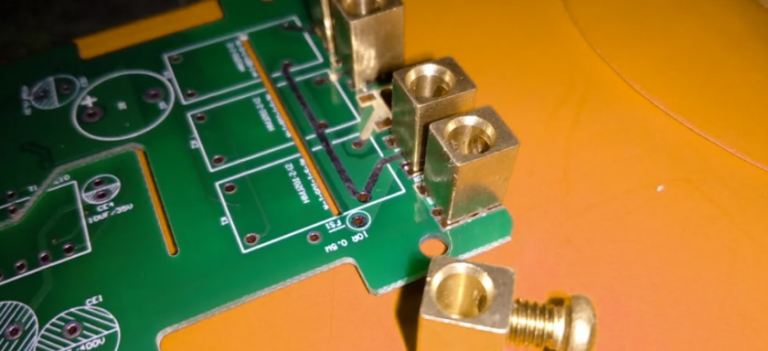
Insertion loss comparisons of common high frequency pcb constructions
Comparative Analysis Of Insertion Loss In FR-4 And Rogers PCB Materials
In the realm of high-frequency printed circuit board (PCB) design, the choice of substrate material plays a pivotal role in determining the overall performance of the circuit. Among the myriad of materials available, FR-4 and Rogers are two of the most commonly used substrates, each offering distinct characteristics that influence insertion loss.
Insertion loss, a critical parameter in high-frequency applications, refers to the loss of signal power resulting from the insertion of a device in a transmission line. Understanding the comparative insertion loss of these materials is essential for engineers aiming to optimize the performance of their high-frequency circuits.
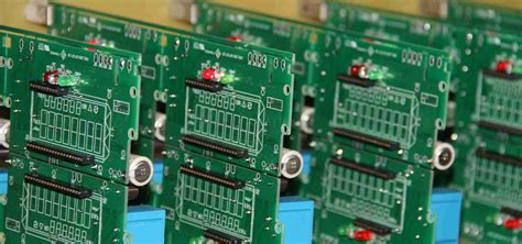
FR-4, a widely used material in PCB manufacturing, is known for its cost-effectiveness and versatility.
It is composed of woven fiberglass cloth with an epoxy resin binder, which provides a good balance of mechanical strength and electrical insulation.
However, when it comes to high-frequency applications, FR-4 exhibits higher insertion loss compared to specialized materials like Rogers. This is primarily due to its higher dielectric constant and loss tangent, which contribute to greater signal attenuation at elevated frequencies. Consequently, while FR-4 is suitable for a broad range of applications, its performance may be suboptimal in scenarios where minimizing insertion loss is critical.
On the other hand, Rogers materials are specifically engineered for high-frequency applications, offering superior electrical properties that result in lower insertion loss.
These materials are characterized by a lower dielectric constant and loss tangent, which significantly reduce signal attenuation. As a result, Rogers substrates are often preferred in applications such as microwave circuits, RF communication systems, and high-speed digital circuits, where maintaining signal integrity is paramount. The reduced insertion loss in Rogers materials can be attributed to their homogeneous composition and the use of advanced resin systems that minimize dielectric losses.
Transitioning from the general characteristics of these materials to a more detailed comparison, it is important to consider the frequency-dependent nature of insertion loss.
At lower frequencies, the difference in insertion loss between FR-4 and Rogers may be negligible. However, as the frequency increases, the disparity becomes more pronounced. For instance, at frequencies above 1 GHz, the insertion loss in FR-4 can increase significantly, leading to degraded signal quality and potential performance issues. In contrast, Rogers materials maintain a relatively stable insertion loss across a wide frequency range, making them more suitable for high-frequency applications.
Furthermore, the choice between FR-4 and Rogers is not solely dictated by electrical performance.
Cost considerations also play a crucial role in material selection. While Rogers materials offer superior performance, they are generally more expensive than FR-4. Therefore, engineers must weigh the benefits of reduced insertion loss against the increased material costs. In applications where budget constraints are a primary concern, FR-4 may still be a viable option, provided that the insertion loss is within acceptable limits for the specific application.
In conclusion, the comparative analysis of insertion loss in FR-4 and Rogers PCB materials highlights the trade-offs between cost and performance in high-frequency applications. While FR-4 offers a cost-effective solution with acceptable performance at lower frequencies, Rogers materials provide superior electrical properties that minimize insertion loss at higher frequencies. Ultimately, the choice of substrate material should be guided by the specific requirements of the application, balancing the need for low insertion loss with budgetary constraints.
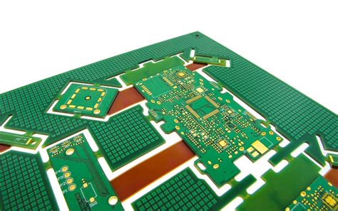
Evaluating Insertion Loss In High-Frequency PCBs: PTFE Vs. Ceramic-Filled Substrates
In the realm of high-frequency printed circuit boards (PCBs), the evaluation of insertion loss is a critical factor that influences the overall performance of electronic devices. Insertion loss, which refers to the loss of signal power resulting from the insertion of a device in a transmission line, is particularly significant in high-frequency applications where signal integrity is paramount. Among the various materials used in the construction of high-frequency PCBs, polytetrafluoroethylene (PTFE) and ceramic-filled substrates are two of the most prevalent. Understanding the differences in insertion loss between these materials is essential for engineers and designers aiming to optimize the performance of their electronic systems.
PTFE, commonly known by the brand name Teflon, is a popular choice for high-frequency PCB applications due to its excellent dielectric properties and low loss tangent.
These characteristics make PTFE an ideal candidate for minimizing insertion loss, as it allows signals to propagate with minimal attenuation. However, PTFE’s inherent flexibility and thermal expansion properties can pose challenges in maintaining dimensional stability, which can, in turn, affect the consistency of insertion loss across different operating conditions. Despite these challenges, PTFE remains a favored material for applications where low insertion loss is a priority, such as in microwave and RF circuits.
On the other hand, ceramic-filled substrates offer an alternative with distinct advantages and trade-offs.
These materials are typically composed of a polymer matrix filled with ceramic particles, which enhance the substrate’s mechanical stability and thermal conductivity. The presence of ceramic fillers can lead to a higher dielectric constant compared to PTFE, which may result in increased insertion loss. However, the improved thermal management and dimensional stability of ceramic-filled substrates can offset this disadvantage by providing more consistent performance over a wide range of temperatures and frequencies. This makes ceramic-filled substrates particularly suitable for applications where environmental stability is as crucial as minimizing insertion loss.
When comparing the insertion loss characteristics of PTFE and ceramic-filled substrates, it is important to consider the specific requirements of the application.
For instance, in scenarios where the utmost signal integrity is required, such as in high-speed data communication systems, PTFE’s lower insertion loss may be the deciding factor. Conversely, in applications where the operating environment is subject to significant temperature fluctuations or mechanical stress, the robustness of ceramic-filled substrates may outweigh the slightly higher insertion loss.
Moreover, advancements in material science have led to the development of hybrid substrates that combine the benefits of both PTFE and ceramic-filled materials.
These hybrid constructions aim to achieve a balance between low insertion loss and enhanced mechanical and thermal properties, offering a versatile solution for a wide range of high-frequency applications. As technology continues to evolve, the ongoing research and development in substrate materials will likely yield even more options for optimizing insertion loss in high-frequency PCBs.
In conclusion, the choice between PTFE and ceramic-filled substrates for high-frequency PCBs involves a careful consideration of the trade-offs between insertion loss and other performance factors. By understanding the unique properties and limitations of each material, engineers can make informed decisions that align with the specific demands of their applications, ultimately enhancing the performance and reliability of their electronic systems.

Insertion Loss Performance: Comparing Hybrid PCB Constructions
In the realm of high-frequency printed circuit boards (PCBs), insertion loss is a critical parameter that significantly impacts the performance of electronic devices. As technology advances, the demand for PCBs that can efficiently handle high-frequency signals has increased, necessitating a closer examination of the insertion loss characteristics of various PCB constructions. Insertion loss, which refers to the loss of signal power resulting from the insertion of a device in a transmission line, is influenced by several factors, including the materials used, the design of the PCB, and the frequency of operation.
Therefore, understanding how different hybrid PCB constructions compare in terms of insertion loss is essential for engineers and designers aiming to optimize the performance of high-frequency applications.
Hybrid PCB constructions, which combine different materials to achieve desired electrical and mechanical properties, have become increasingly popular in high-frequency applications.
These constructions often involve a combination of low-loss dielectric materials and standard FR-4 substrates. The choice of materials plays a pivotal role in determining the insertion loss characteristics of the PCB. For instance, materials with lower dielectric constants and dissipation factors tend to exhibit lower insertion loss, making them suitable for high-frequency applications. However, the cost and manufacturability of these materials must also be considered, as they can significantly impact the overall feasibility of the PCB design.
When comparing the insertion loss performance of hybrid PCB constructions, it is important to consider the frequency range over which the PCB will operate.
At lower frequencies, the insertion loss is primarily influenced by the conductive losses in the copper traces and the dielectric losses in the substrate material. As the frequency increases, however, the skin effect becomes more pronounced, leading to higher insertion losses.
This is because the current tends to concentrate near the surface of the conductor at higher frequencies, effectively reducing the cross-sectional area available for current flow and increasing the resistance. Consequently, hybrid constructions that utilize materials with lower surface roughness and optimized copper plating techniques can help mitigate these effects and reduce insertion loss at high frequencies.
Moreover, the design of the PCB, including the trace width, spacing, and layer stack-up, also plays a significant role in determining insertion loss.
For example, wider traces can reduce resistive losses, while careful control of the spacing between traces can minimize crosstalk and other parasitic effects that contribute to insertion loss. Additionally, the use of advanced fabrication techniques, such as laser-drilled microvias and sequential lamination, can further enhance the performance of hybrid PCB constructions by reducing signal path lengths and improving impedance matching.
In conclusion, the insertion loss performance of hybrid PCB constructions is a complex interplay of material properties, design considerations, and fabrication techniques. By carefully selecting materials with favorable dielectric properties, optimizing the PCB design for high-frequency operation, and employing advanced manufacturing processes, engineers can significantly reduce insertion loss and improve the overall performance of high-frequency PCBs.
As the demand for high-speed, high-frequency electronic devices continues to grow, the ability to effectively manage insertion loss will remain a key factor in the successful design and implementation of hybrid PCB constructions.

Impact Of Copper Surface Roughness On Insertion Loss In High-Frequency PCBs
In the realm of high-frequency printed circuit boards (PCBs), insertion loss is a critical parameter that significantly impacts the performance of electronic devices. Insertion loss refers to the loss of signal power resulting from the insertion of a device in a transmission line, and it is influenced by various factors, including the construction materials and techniques used in PCB manufacturing.
Among these factors, copper surface roughness plays a pivotal role in determining the extent of insertion loss in high-frequency applications. Understanding the impact of copper surface roughness on insertion loss is essential for optimizing PCB designs and ensuring efficient signal transmission.
Copper, being a primary conductor in PCBs, is often subjected to surface treatments to enhance adhesion with dielectric materials.
However, these treatments can introduce surface roughness, which, in turn, affects the electromagnetic properties of the copper layer. As frequency increases, the skin effect becomes more pronounced, causing current to flow primarily on the surface of the conductor. Consequently, any irregularities on the copper surface can lead to increased resistance and, thus, higher insertion loss. This phenomenon is particularly significant in high-frequency applications, where even minor variations in surface texture can result in substantial signal degradation.
To mitigate the adverse effects of copper surface roughness, PCB manufacturers employ various techniques to smooth the copper surface.
One common approach is the use of low-profile copper foils, which are designed to have minimal surface roughness. These foils are engineered to provide a smoother interface with the dielectric material, thereby reducing the skin effect and minimizing insertion loss. Additionally, advanced plating techniques, such as electroless nickel immersion gold (ENIG) and organic solderability preservatives (OSP), are utilized to achieve a more uniform copper surface. These methods not only enhance the electrical performance of the PCB but also improve its overall reliability and longevity.
Comparative studies of different high-frequency PCB constructions reveal that the choice of copper foil and surface treatment can significantly influence insertion loss characteristics.
For instance, PCBs constructed with ultra-smooth copper foils exhibit lower insertion loss compared to those using standard copper foils. This is attributed to the reduced surface roughness, which minimizes the scattering of electromagnetic waves and enhances signal integrity. Furthermore, the integration of advanced dielectric materials with low dielectric constants and dissipation factors can complement the benefits of smooth copper surfaces, leading to further reductions in insertion loss.
In addition to material selection, the manufacturing process itself can impact copper surface roughness and, consequently, insertion loss.
Techniques such as laser ablation and precision etching are employed to achieve finer control over the copper surface profile. These processes allow for the creation of intricate circuit patterns with minimal surface irregularities, thereby optimizing the electrical performance of high-frequency PCBs. Moreover, ongoing research and development efforts are focused on exploring novel materials and fabrication methods to further reduce insertion loss and enhance the performance of high-frequency electronic devices.
In conclusion, the impact of copper surface roughness on insertion loss in high-frequency PCBs is a critical consideration for designers and manufacturers aiming to optimize signal transmission. By selecting appropriate materials and employing advanced manufacturing techniques, it is possible to minimize insertion loss and improve the overall performance of high-frequency PCBs. As technology continues to advance, the quest for smoother copper surfaces and more efficient PCB constructions will remain a key focus in the pursuit of superior electronic performance.

