Fr4 flex pcb
Advantages Of Using FR4 Flex PCB In Modern Electronics
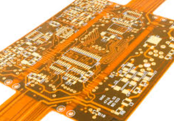
FR4 flex PCBs, or flexible printed circuit boards, have become a cornerstone in the development of modern electronics, offering a multitude of advantages that cater to the evolving demands of technology. As electronic devices continue to shrink in size while expanding in functionality, the need for components that can accommodate these changes has never been more critical. FR4 flex PCBs, with their unique properties, provide an ideal solution for manufacturers seeking to enhance the performance and reliability of their products.
One of the primary advantages of using FR4 flex PCBs is their exceptional flexibility.
Unlike traditional rigid PCBs, flex PCBs can bend and twist, allowing them to fit into compact and irregularly shaped spaces. This flexibility is particularly beneficial in applications such as wearable technology, medical devices, and automotive electronics, where space is often at a premium. By enabling more efficient use of available space, FR4 flex PCBs contribute to the miniaturization of electronic devices, a trend that is increasingly prevalent in today’s market.
In addition to their flexibility, FR4 flex PCBs offer significant weight reduction compared to their rigid counterparts.
The lightweight nature of these PCBs is advantageous in applications where weight is a critical factor, such as in aerospace and portable consumer electronics. By reducing the overall weight of a device, manufacturers can improve energy efficiency and enhance the user experience, particularly in battery-powered devices where every gram counts.
Moreover, FR4 flex PCBs are known for their durability and reliability.
The materials used in their construction, including the FR4 substrate, provide excellent thermal stability and resistance to environmental stressors such as moisture and temperature fluctuations. This robustness ensures that devices can operate effectively in challenging conditions, making FR4 flex PCBs suitable for use in a wide range of industries, from industrial automation to telecommunications.
Another notable advantage of FR4 flex PCBs is their ability to reduce the complexity of electronic assemblies.
By integrating multiple components and interconnections into a single flexible circuit, these PCBs can simplify the design and manufacturing process. This integration not only reduces the number of potential failure points but also decreases assembly time and costs. Consequently, manufacturers can achieve higher production efficiency and deliver products to market more quickly.
Furthermore, the use of FR4 flex PCBs can lead to improved signal integrity and performance.
The flexible nature of these PCBs allows for shorter and more direct routing of electrical signals, minimizing the risk of signal loss or interference. This characteristic is particularly important in high-frequency applications, where maintaining signal quality is crucial for optimal device performance.
In conclusion, the advantages of using FR4 flex PCBs in modern electronics are manifold. Their flexibility, lightweight nature, durability, and ability to simplify electronic assemblies make them an invaluable component in the design and manufacture of cutting-edge devices. As technology continues to advance, the demand for innovative solutions like FR4 flex PCBs is likely to grow, driving further developments in the field and enabling the creation of even more sophisticated electronic products. By embracing these advancements, manufacturers can ensure that they remain at the forefront of the industry, delivering high-quality, reliable, and efficient solutions to meet the needs of an ever-evolving market.
Design Considerations For FR4 Flex PCB Applications
When designing FR4 flex PCBs, several critical considerations must be taken into account to ensure optimal performance and reliability. FR4, a widely used material in the electronics industry, is known for its excellent mechanical strength and electrical insulation properties. However, when used in flexible PCB applications, it presents unique challenges that require careful attention to design details.
To begin with, understanding the material properties of FR4 is essential.
FR4 is a glass-reinforced epoxy laminate that provides rigidity and stability, making it ideal for traditional rigid PCBs. However, its inherent stiffness can be a limitation in flexible applications. Therefore, designers must consider the bending requirements of the application and ensure that the FR4 flex PCB can withstand the necessary flexing without compromising its structural integrity. This often involves selecting the appropriate thickness and layer stack-up to balance flexibility with durability.
Moreover, the choice of copper thickness is another crucial factor.
Thicker copper layers can enhance current-carrying capacity but may reduce flexibility. Conversely, thinner copper layers improve flexibility but may not support high current loads. Therefore, designers must carefully evaluate the electrical requirements of the application and choose a copper thickness that provides an optimal balance between flexibility and electrical performance.
In addition to material selection, the layout of the circuit traces plays a significant role in the design of FR4 flex PCBs.
Trace routing should be optimized to minimize stress during bending. This can be achieved by using curved traces instead of sharp angles, which can act as stress concentrators and lead to potential failure points. Furthermore, maintaining consistent trace widths and spacing is crucial to ensure uniform electrical characteristics and prevent issues such as impedance mismatches.
Thermal management is another important consideration in FR4 flex PCB design.
The thermal conductivity of FR4 is relatively low, which can lead to heat buildup in high-power applications. To address this, designers can incorporate thermal vias or heat sinks to dissipate heat effectively. Additionally, careful placement of components and strategic use of thermal reliefs can help manage heat distribution across the PCB.
Signal integrity is also a key aspect that must be addressed during the design process.
High-speed applications require careful attention to signal integrity to prevent issues such as crosstalk and electromagnetic interference. This can be achieved by maintaining controlled impedance, using differential pairs for critical signals, and implementing proper grounding techniques. Additionally, the use of simulation tools can aid in predicting and mitigating potential signal integrity issues before the PCB is fabricated.
Finally, manufacturability and cost considerations should not be overlooked.
While FR4 flex PCBs offer numerous advantages, they can be more challenging and costly to manufacture compared to traditional rigid PCBs. Therefore, designers should work closely with manufacturers to ensure that the design is optimized for production, taking into account factors such as panel utilization, yield, and assembly processes.
In conclusion, designing FR4 flex PCBs requires a comprehensive understanding of material properties, electrical and thermal requirements, and manufacturing constraints. By carefully considering these factors and employing best practices in layout and design, engineers can create reliable and efficient FR4 flex PCB solutions that meet the demands of modern electronic applications.
Manufacturing Process Of FR4 Flex PCB: A Step-By-Step Guide
The manufacturing process of FR4 flex PCBs, a crucial component in modern electronics, involves a series of meticulously coordinated steps that ensure the final product meets the high standards required for performance and reliability. Understanding this process is essential for those involved in electronics design and production, as it provides insight into how these versatile circuit boards are created.
To begin with, the process starts with the selection of materials.
FR4, a composite material made from woven fiberglass cloth with an epoxy resin binder, is chosen for its excellent mechanical strength and electrical insulation properties. This material serves as the substrate for the PCB. The flexibility of the board is achieved by incorporating flexible layers, typically made from polyimide, which allows the board to bend and conform to various shapes without compromising its functionality.
Once the materials are selected, the next step involves designing the circuit layout.
This is done using specialized software that allows engineers to create precise and intricate designs tailored to the specific requirements of the application. The design is then transferred onto the FR4 substrate through a process known as photolithography. In this step, a photosensitive film is applied to the substrate, and the circuit pattern is exposed onto it using ultraviolet light. The exposed areas are then developed, leaving behind a detailed pattern that will guide the subsequent etching process.
Following the photolithography, the board undergoes an etching process.
This involves immersing the board in a chemical solution that removes the unwanted copper, leaving behind only the desired circuit traces. The precision of this step is critical, as any errors can lead to faulty circuits. After etching, the board is thoroughly cleaned to remove any residual chemicals and debris.
The next phase involves drilling holes for component leads and vias, which are essential for establishing electrical connections between different layers of the PCB.
This is accomplished using computer-controlled drilling machines that ensure accuracy and consistency. Once the holes are drilled, they are plated with copper to create conductive pathways.
Subsequently, the board undergoes a solder mask application.
This protective layer is applied over the copper traces to prevent short circuits and corrosion. The solder mask is typically green, although other colors are available, and it is applied using a screen-printing process. After the solder mask is cured, a silkscreen layer is added to print component labels and other necessary markings on the board.
The final steps in the manufacturing process involve testing and quality control.
Each board is subjected to rigorous testing to ensure it meets the required specifications and functions correctly. This includes electrical testing to verify the integrity of the circuits and visual inspections to check for any physical defects. Any boards that fail to meet the standards are rejected or reworked.
In conclusion, the manufacturing process of FR4 flex PCBs is a complex and precise operation that requires careful attention to detail at every stage. From material selection and circuit design to etching, drilling, and testing, each step is crucial in producing a reliable and high-quality product. Understanding this process not only highlights the intricacies involved in PCB production but also underscores the importance of quality control in ensuring the performance and longevity of electronic devices.
Comparing FR4 Flex PCB With Other Flexible PCB Materials
In the realm of modern electronics, the choice of materials for printed circuit boards (PCBs) plays a crucial role in determining the performance, reliability, and cost-effectiveness of the final product. Among the various options available, FR4 flex PCBs have emerged as a popular choice due to their unique combination of flexibility and durability.
However, to fully appreciate the advantages and limitations of FR4 flex PCBs, it is essential to compare them with other flexible PCB materials, such as polyimide and polyester, which are also widely used in the industry.
FR4, a composite material made from woven fiberglass cloth with an epoxy resin binder, is renowned for its excellent mechanical strength and electrical insulation properties.
When used in flexible PCBs, FR4 offers a robust solution that can withstand significant mechanical stress and environmental factors. This makes it particularly suitable for applications where durability is paramount, such as in automotive and industrial electronics. However, while FR4 flex PCBs provide a good balance of flexibility and rigidity, they are not as flexible as some other materials, which can be a limitation in applications requiring extreme bending or folding.
In contrast, polyimide is another popular material used in flexible PCBs, known for its exceptional thermal stability and flexibility.
Polyimide flex PCBs can endure higher temperatures and more severe bending than their FR4 counterparts, making them ideal for applications in aerospace and military electronics, where extreme conditions are common. Additionally, polyimide’s excellent chemical resistance further enhances its suitability for harsh environments. However, these advantages come at a cost, as polyimide is generally more expensive than FR4, which can be a significant consideration for cost-sensitive projects.
Similarly, polyester is another alternative material used in flexible PCBs, offering a cost-effective solution with good flexibility and moderate thermal resistance.
Polyester flex PCBs are often used in consumer electronics, where cost efficiency is a primary concern, and the environmental conditions are less demanding. While polyester provides adequate performance for many applications, it lacks the high-temperature tolerance and mechanical strength of both FR4 and polyimide, which can limit its use in more demanding environments.
When comparing FR4 flex PCBs with these alternative materials, it is important to consider the specific requirements of the application.
For instance, if the primary concern is cost and the environmental conditions are not extreme, polyester may be the most suitable choice. On the other hand, if the application demands high thermal resistance and flexibility, polyimide would likely be the better option. However, for applications that require a balance of mechanical strength, electrical insulation, and moderate flexibility, FR4 flex PCBs offer a compelling solution.
In conclusion, the choice between FR4 flex PCBs and other flexible PCB materials depends largely on the specific needs of the application, including factors such as cost, environmental conditions, and mechanical requirements. By carefully evaluating these factors, designers can select the most appropriate material to ensure optimal performance and reliability of the final product. As technology continues to advance, the development of new materials and manufacturing techniques will further expand the possibilities for flexible PCBs, offering even greater versatility and performance in the future.