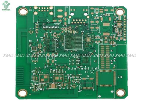
Repair of circuit boards by inverter repair instrument without schematic diagram
To repair a relatively unfamiliar circuit board without any schematic diagram, the so-called “experience” in the past will be difficult to achieve. Although people with a solid hardware foundation are confident in repair, if the method is not appropriate, the work will still be ineffective. So, how can we improve the efficiency of repair? According to the statistics of our company’s imported equipment maintenance center, we should follow the following principles to proceed in an orderly manner in steps and in sequence.
Principle 1: Look first and then measure
Tools used: multimeter, magnifying glass
When holding a circuit board to be repaired, a good habit is to visually inspect it first, and use a magnifying glass when necessary. What to look at?
Mainly look at:
- Is there a broken wire;
- There is a disconnection phenomenon when the force-dividing components such as resistors, electrolytic capacitors, inductors, diodes, transistors, etc.;
- Is there a break or adhesion in the printed circuit board connection wires on the circuit board;
- Has anyone repaired it? Which components have been moved? Are there any operational errors such as cold soldering, leaky soldering, reverse insertion, etc.?
After confirming that the repaired board does not have the above conditions, first use a multimeter to measure the resistance between the power supply and the ground of the circuit board. Usually, the resistance of the circuit board is above 70-80? If the resistance is too small, only a few or a dozen ohms, it means that there are components on the circuit board that are broken down or partially broken down, and measures must be taken to find the broken components. The specific method is to power the repaired board and touch the temperature of each component on the circuit board with your hand. The lecturer who is hot will focus on the suspected object. If the resistance is normal, use a multimeter to measure the resistors, diodes, transistors, field effect transistors, and dial switches on the board. The purpose is to first ensure that the measured components are normal. Our reason is that if a problem can be solved with a multimeter, don’t complicate it.

Principle 2: First the outside and then the inside
Tools used: HY online circuit repair instrument
If the situation allows, it is best to find a good board that is the same as the repaired board as a reference, and then use the dual-rod VI curve scanning function to compare the two boards. The starting point of comparison can be from the port, and then from the outside to the inside, especially the comparison test of the capacitor, which can make up for the shortcoming that the multimeter is difficult to detect whether it is leaking online.
Principle 3: First the easy and then the difficult
Tools used: HY online circuit repair instrument, electric soldering iron, marker
In order to improve the test effect, before the online functional test of the circuit board, some technical processing should be done on the repaired board to minimize the negative impact of various interferences on the test process. The specific measures are:
- Preparation before the test
Short-circuit the crystal oscillator, and solder a leg of the large electrolytic capacitor to open it, because the charging and discharging of the capacitor can also cause interference.
- Use the elimination method to test the device
During the process of online testing or comparison of the device, for all devices that have passed the test (or are relatively normal), please directly confirm the test results for recording; for those that have not passed the test (or are relatively out of tolerance), you can test them again. If they still fail, you can also confirm the test results first, and continue testing until all the devices on the board are tested (or compared), and then go back to deal with those devices that have not passed the test (or are relatively out of tolerance). For devices that have not passed the functional online test, the instrument also provides a less formal but more practical processing method. Since the instrument can apply the power supply of the circuit board to the corresponding power supply and ground pins of the device through the test clip, if the power supply pin of the device is cut, the device will be separated from the circuit board power supply system. At this time, the device will be tested online. Since other devices on the circuit board will no longer interfere, the actual test effect is equivalent to “quasi-offline”, and the accuracy rate will be greatly improved.
- Use ASA-VI curve scanning test to compare devices that are not covered by the test library
Since ASA-VI intelligent curve scanning technology can be applied to the comparison test of any device, as long as the test clip can clamp the device and there is a reference board, through comparative testing, it also has a strong fault detection capability for the device. This function makes up for the deficiency that the online functional test of the device is subject to the test library, and expands the detection range of the instrument for circuit board faults. In reality, there are often situations where it is impossible to find a good board for reference, and the circuit structure of the board to be repaired itself has no symmetry. In this case, the ASA-VI curve scanning comparison test function does not work, and the online functional test cannot complete the test of every device on the circuit board due to the incomplete device test library, and the circuit board still cannot be repaired. This is the limitation of the circuit online repair instrument, just like there is no medicine that can cure all diseases.
Principle 4: Static first, then dynamic
Since the online circuit repair instrument can only perform online functional testing and static characteristic analysis on the components on the circuit board, whether it is completely repaired must be tested by the whole machine. Therefore, it is best to first check whether the power supply of the equipment is correctly supplied to the circuit board as required.


