What are the safety and security considerations in embedded vision?
The widespread use of embedded vision (EV) systems has become ubiquitous, with advanced driver assistance systems (ADAS), machine vision, medical imaging, augmented reality, and many other applications all requiring an embedded system platform.
However, while adopting EV systems can bring obvious advantages to the end application, it is also incumbent on developers to ensure that the use of the system will not cause personal injury or property damage. This requires not only design safety, strict adherence to engineering life cycles and recognized standards, but also the confidentiality of the EV system to prevent malicious or other modifications.
The end application of the EV system is a driving factor in the strength of the safety and security requirements.
For example, consumer applications have much lower safety and security requirements than ADAS or machine vision systems.
To assist us with these design considerations and safety and security requirements, the industry has developed several well-known international standards (such as IEC61508) to protect many electronic systems that require functional safety. There are also more specialized standards such as ISO26262 for automotive applications, IEC62061 for machinery and DO178/DO254 for aviation applications. In addition, commercial applications require CE, UL or CSA markings depending on the end market. Each of these standards has corresponding development and verification requirements that need to be implemented in the engineering design and delivery life cycle of the organization to ensure compliance.
At the heart of the EV system is the processing core, which generally uses an FPGA or programmable SoC to solve the range of problems currently being raised.
What do these standards actually mean?
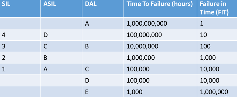
Many of these safety standards define safety levels using different names, such as “Safety Integrity Level” (SIL) for IEC61508, “Design Assurance Level” (DAL) for DO254, and “Automotive SIL” (ASIL) for ISO26262. Within SIL, DAL and ASIL are a range of different levels that can be used depending on the criticality of the application. Generally, these levels are defined in terms of failure time (hours), or more accurately, “failure time (hours)”. While these various standards are generally consistent, there are differences as described below.
Safety Standards and Different Levels
When performing a design analysis, you demonstrate how to achieve the level required for certification. Engineers are accustomed to using the failure in time (FIT) rate, which is the inverse of failure time (hours). This requires a properly architected system to achieve these requirements when operating at SIL4 and DAL A safety levels.
System Considerations
The development of safety systems requires excellent systems engineering design, coupled with well-defined and traceable requirements at each level of development.
As mentioned above, the engineering lifecycle is driven by the end application and the resulting certification required. This lifecycle will determine the overall engineering approach taken from concept, production, to disposal of the EV system.
Within this lifecycle, you can define engineering review gates to control the progress of the project. In these reviews, independent technical experts review the requirements, designs, technical reports, and test results to ensure that the design is mature enough to move to the next stage or that further work is required to achieve the required compliance standards.
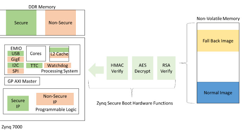
Figure 1: Example of a delivery and engineering lifecycle
The engineering plan should also outline the verification and validation processes at each level that will be performed to obtain evidence of compliance with applicable standards. This may require testing the EV system under various environmental operating ranges, dynamic vibration and shock. You may even have to subject the EV system to accelerated life testing to ensure that the system’s useful life can be achieved.
When it comes to confidentiality, you must consider a range of aspects, which are high-level issues that engineers face when trying to ensure the security of their designs. These aspects include the following:
- Reverse engineering of the design by competitors
- Unauthorized changes to the design
- Unauthorized access to data in the design
- Unauthorized control or manipulation of the end application
There are a number of ways you can address some of these challenges. You can use encrypted bitstreams to control access to design and manufacturing files. Or you can protect the physical design by limiting access to the JTAG port of the end product and implementing software confidentiality measures depending on the architecture of the device you choose.
High-quality design
Obviously you need to consider the components and manufacturing standards you choose based on the end application to ensure that you meet the quality requirements of the application. For the processing cores, you can use Xilinx FPGA and SoC devices that meet grades for both standard commercial quality standards and more stringent standards for industrial, automotive, aerospace and military applications. This allows engineering teams to improve quality from the start by selecting the right grade of components.
In addition, there are a range of design techniques you can use to help meet the stringent requirements of these standards. To help ensure that you meet reliability requirements (often referred to as probability of success), you can use reliability engineering techniques, if necessary, to create reliability block diagrams for each function in the system and ensure that any dangerous failure modes and single point failures are avoided. Within the design itself, you can perform a Failure Mode Effects and Criticality Analysis (FMECA). The level at which this analysis is performed can vary from the functional block level down to the component level, depending on the application. The FMECA will consider potential failure modes, aftereffects, and ultimate impact on the system, and it will also consider whether the failure can be detected by built-in self-test and monitoring systems. If you are developing a component-level FMECA, you will need to consider a Part Stress Analysis (PSA) of each component in the design to ensure that the components are operating under the correct de-rating conditions. The level of de-rating for your application will depend on the common standard selected. Standards include those from the Department of Defense (Mil-STD 1547) and the European Space Agency (ESCC-Q-30-11A). If you don’t perform a PSA analysis, you could be operating devices in overstressed conditions that could become life-limiting. Failure of these devices may or may not result in loss of system or performance degradation, as predicted by FMECA.
While analyzing reliability, you can also perform a threat analysis on the system to identify system threats based on the use case and possible mitigation strategies for the identified threats.
Architecture Case Analysis
At the hardware level, you need to consider the functionality of the system and how you can achieve functional safety and security. While this can be done from scratch, a better approach is to select components that already support these capabilities, such as the Xilinx Zynq® All Programmable SoC.
At the heart of any EV system is the image processing pipeline. This requires high-bandwidth processing combined with monitoring and control capabilities. The Zynq All Programmable SoC allows us to have a tightly integrated architecture compared to the traditional processor and FPGA combination.
This tighter integration between the processor and logic fabric not only results in a better SAWP-C solution, it also provides a more secure system because the interactions between the processor and logic fabric are not exposed to the outside world, allowing for malicious or other access.
Within the electronics architecture, you can use the Zynq All Programmable SoC’s embedded security architecture to provide secure configuration capabilities. In both the programmable system (PS) and programmable logic (PL), you can use a three-phase approach to secure system partitions. The three-phase approach includes a hashed message authentication code (HMAC), Advanced Encryption Standard (AES) decryption, and RSA authentication. Both AES and HMAC use a 256-bit private key, while RSA uses a 2,048-bit key. Zynq All Programmable SoC’s security architecture also allows JTAG access to be enabled or disabled.
These security features are enabled when you generate the boot files and configuration partitions for our non-volatile boot media. You can also define a rollback partition so that if the initial first-stage boot loader fails to load its application, it can roll back to another copy of the application stored in a different memory location.
Once you have your device up and running, we can use the ARM Trust Zone architecture to implement orthogonal environments that restrict access to hardware functions within the Zynq AP SoC, including programmable logic (PL) peripherals. You can also segment memory and L2 cache to ensure that interactions between secure and non-secure environments are restricted.
Zynq AP SoC Secure Boot and Trust Zone Implementation
If you are implementing an image processing pipeline in the programmable logic fabric of the Zynq AP SoC, you can also use Trust Zone to provide secure or non-secure access to IP cores in the programmable logic fabric. This allows you to provide secure access to critical aspects of the image processing chain and prevent unauthorized changes to the configuration.
The image processing pipeline can be implemented using custom developed modules or modules from an IP library.
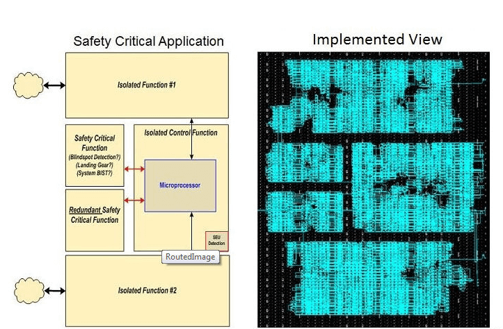
Some safety and security implementations, such as IEC61508, may require design elements to be isolated from each other, which may be the result of building in module redundancy, distinguishing secure areas, or testing functionality. By using the Isolation Design Flow (IDF), you can enforce physical isolation between identified areas. This is supported for Zynq devices when using the Vivado® Design Suite.
IDF Mandatory Policies for Safety-Critical FPGAs
If you want to implement majority voting in a processing chain or other control logic, the isolation design flow is useful for you. Using the isolation design flow ensures that the only interconnections between redundant modules are implemented through trusted paths.
There are a number of device- and tool-specific design considerations that you need to consider when implementing your design. Of course, the end application and your overall engineering management plan will determine the need to adopt these techniques.
- Use error detection and correction (EDAC) codes on memory. This can be combined with the erase function to periodically read and correct the data in the memory when necessary, regardless of whether the application is accessing the memory.
- Apply Hamming code differences when defining control words, increasing the Hamming distance between command words while requiring more bits to be implemented, which helps improve the reliability of the design.
- Use the ARM and FIRE method for critical commands, which requires two separate commands for action-critical functions.
- Use EDAC codes on external communication interfaces
- Comprehensive built-in-test (BIT) capabilities to report system health or other statusThe Zynq XADC is a very powerful component of the BIT system because it enables device voltage and temperature monitoring by introducing external signals through multiplexers.
Summary
Applying the right functional safety industry standards to your embedded vision system is possible, and there are a number of components, tools, and development methodologies available to system developers.
To ensure we meet the certification requirements for your EV system, you need to correctly determine the applicable standards from the beginning of the design and generate an engineering management plan that defines the engineering life cycle to collect the evidence required for certification.