Advanced Topology for System-Level Test and PCB Configuration
The SELEX airborne radar discussed in this article uses a scalable design with a dynamically reconfigurable active backplane to serve multiple vector computing (VP) boards. Such a design can use the intelligent backplane to degrade service by shutting down the power to the suspect board when a board failure occurs. The main communication processor allows access to the VP board through the EFA bus standard, radar bus interface, receiver interface, and video interface.
In the test system, the NI PCI-6533 is used as the interface to the EMId (Electronic Module Identification) devices located on each SRI (Store Replaceable Unit).
They carry part number and serial number data, etc., and also include a log of recent fault detection. The PCI-DIO-96 is used as a 160-pin DIO using a CPLD that multiplexes the output and input of the I/O board from the test controller PC. The system includes optional input event blocking (for capturing transient events) and all bidirectional operations. 16 I/O pins are used for control and status signals CONTROL ENGINEERING China Copyright, while the other 80 pins are multiplexed to provide 160 outputs and 160 inputs for emulation and testing of digital interfaces.
JTAG/Boundary Scan testing and ISP (In-System Programming) are the core parts of the system and are now considered the primary means for checking whether there are assembly faults on printed circuit boards (PCBs) and systems in production and prototype development debugging, as well as field service faults in released equipment.
Boundary Scan testing relies on built-in test circuits and modern highly integrated electronic devices (compatible with IEEE Standard 1149.1).
Boundary Scan testing requires a minimum test interface consisting of four or five digital interfaces. This is in stark contrast to the huge CONTROL ENGINEERING China Copyright of traditional nail board test systems, which require hundreds or even thousands of test probe connections.
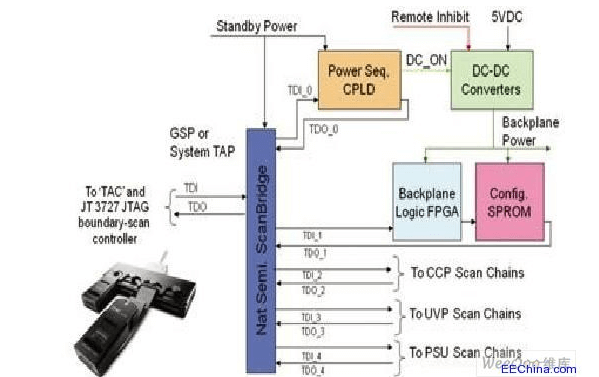
Thus, the boundary scan tester is reduced to the size of a serial protocol interface unit, which can be provided by a PCI, PXI or compact bench (USB/Ethernet) control unit. Simply adding power to the system can put the autonomous PCB tester into operation. In addition, careful product design using ScanBridge TAP multiplexers can access a series of PCBs in the system with a single controller, thus building a system/LRI (line replaceable article) tester.
The airborne radar makes full use of ScanBridge devices to divide the system into logically accessible modules.
When more peripheral interface hardware such as analog measurement instruments and test signal multiplexers are added to the system, the system is upgraded from a “structured” boundary scan based tester to a full-featured mixed signal test system with integrated test capabilities.