
Reflow Soldering for Double-Sided Printed Circuit Boards (PCBs)
Introduction
Reflow soldering is a widely used process in the electronics manufacturing industry for attaching surface mount components to printed circuit boards (PCBs). This process involves the application of solder paste to the PCB, placement of components, and then heating the assembly to melt the solder, creating reliable electrical and mechanical connections. When it comes to double-sided PCBs, which have components on both sides of the board, the reflow soldering process becomes more complex. This article will explore the challenges, techniques, and best practices for reflow soldering double-sided PCBs.
1. Understanding Double-Sided PCBs
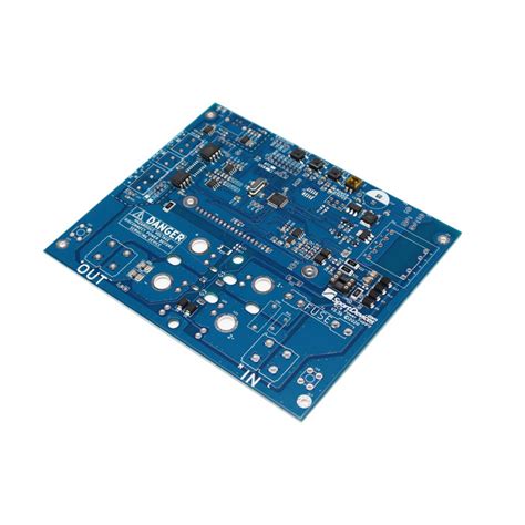
Double-sided PCBs have conductive traces and components on both the top and bottom layers. This design allows for higher component density and more complex circuit designs compared to single-sided PCBs. However, the presence of components on both sides introduces challenges during the reflow soldering process, particularly when it comes to managing heat and ensuring that components on the first side do not fall off or get damaged during the second reflow cycle.
2. The Reflow Soldering Process
The reflow soldering process typically involves the following steps:
- Solder Paste Application: Solder paste, a mixture of tiny solder particles and flux, is applied to the PCB pads using a stencil.
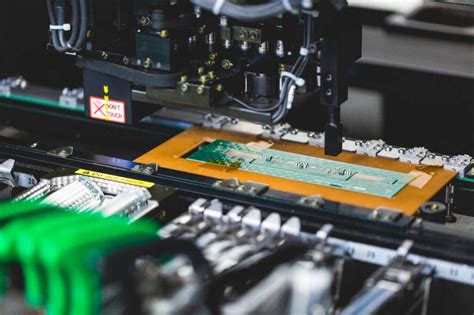
- Component Placement: Surface mount components are placed onto the solder paste using a pick-and-place machine.
- Reflow: The PCB is passed through a reflow oven, where it is subjected to a controlled temperature profile that melts the solder paste, forming solder joints.
- Cooling: The PCB is cooled, solidifying the solder joints and completing the assembly process.
For double-sided PCBs, this process is repeated for each side, with additional considerations to ensure the integrity of the components on the first side during the second reflow cycle.
3. Challenges in Reflow Soldering Double-Sided PCBs
3.1. Component Stability During Second Reflow
One of the primary challenges in reflow soldering double-sided PCBs is ensuring that components on the first side remain securely attached during the second reflow cycle. When the PCB is heated for the second time, the solder joints on the first side may re-melt, causing components to shift or fall off.
3.2. Thermal Management
Managing the thermal profile is critical when reflow soldering double-sided PCBs. The temperature must be high enough to melt the solder paste on the second side without damaging components on the first side. This requires careful control of the reflow oven’s temperature profile, including the preheat, soak, reflow, and cooling phases.
3.3. Solder Paste Selection
The choice of solder paste can significantly impact the success of reflow soldering double-sided PCBs. Low-temperature solder pastes may reduce the risk of re-melting solder joints on the first side, but they may also have lower mechanical strength. Conversely, high-temperature solder pastes may provide stronger joints but increase the risk of damaging components during the second reflow cycle.
4. Techniques for Successful Reflow Soldering of Double-Sided PCBs
4.1. Sequential Reflow
One common approach to reflow soldering double-sided PCBs is to use a sequential reflow process. In this method, the first side is reflowed, and then the second side is reflowed in a separate cycle. To prevent components on the first side from falling off, adhesive can be applied to hold them in place during the second reflow cycle. Alternatively, selective soldering can be used for the second side, where only specific areas are heated to avoid re-melting the solder joints on the first side.
4.2. Dual Reflow
Another technique is the dual reflow process, where both sides of the PCB are reflowed simultaneously. This method requires precise control of the reflow oven’s temperature profile to ensure that both sides reach the appropriate temperature without overheating components on either side. Dual reflow can be more efficient than sequential reflow but requires advanced equipment and careful process optimization.
4.3. Use of Low-Temperature Solder Paste
Using a low-temperature solder paste for the first side can reduce the risk of re-melting during the second reflow cycle. However, as mentioned earlier, low-temperature solder pastes may have lower mechanical strength, so this approach must be carefully evaluated based on the specific requirements of the PCB.
4.4. Component Placement and Design Considerations
Proper component placement and PCB design can also help mitigate the challenges of reflow soldering double-sided PCBs. For example, placing heavier components on the bottom side and lighter components on the top side can reduce the risk of components falling off during the second reflow cycle. Additionally, designing the PCB with thermal reliefs and ensuring adequate spacing between components can help manage heat distribution during reflow.
5. Best Practices for Reflow Soldering Double-Sided PCBs
5.1. Optimize the Reflow Profile
The reflow profile is critical to the success of reflow soldering double-sided PCBs. The profile should be optimized to ensure that the solder paste on both sides reaches the appropriate temperature for melting without overheating components. This may involve adjusting the preheat, soak, reflow, and cooling phases to achieve the desired results.
5.2. Use Adhesive for Component Stability
Applying adhesive to hold components in place during the second reflow cycle can help prevent them from falling off. This is particularly important for heavier components or those with a high center of gravity. The adhesive should be applied in a way that does not interfere with the solder joints or the overall functionality of the PCB.
5.3. Monitor and Control the Reflow Process
Continuous monitoring and control of the reflow process are essential for ensuring consistent results. This includes monitoring the temperature profile, conveyor speed, and oven conditions. Automated systems can be used to track these parameters and make real-time adjustments as needed.
5.4. Perform Regular Maintenance
Regular maintenance of the reflow oven and other equipment is crucial for maintaining consistent performance. This includes cleaning the oven, calibrating temperature sensors, and replacing worn components. Proper maintenance can help prevent defects and ensure the long-term reliability of the reflow soldering process.
6. Conclusion
Reflow soldering double-sided PCBs presents unique challenges due to the presence of components on both sides of the board. However, with careful planning, optimization of the reflow profile, and the use of appropriate techniques and materials, these challenges can be effectively managed. By following best practices and continuously monitoring the reflow process, manufacturers can achieve high-quality solder joints and reliable PCB assemblies, even for complex double-sided designs.
In summary, reflow soldering for double-sided PCBs requires a combination of technical expertise, precise process control, and attention to detail. By understanding the challenges and implementing the right strategies, manufacturers can successfully produce double-sided PCBs that meet the demanding requirements of modern electronic devices.