Optimal 4-Layer PCB Stackup Design for Drone Flight Controllers
Key Takeaways
When designing 4-layer PCBs for drone flight controllers, understanding stackup configuration is critical for balancing performance and PCB manufacturing cost. Proper layer arrangement ensures optimal signal integrity while accommodating power distribution needs. Here’s what to prioritize:
"A well-planned ground plane strategy minimizes electromagnetic interference (EMI) – a common challenge in high-speed drone applications."
- Power Routing: Dedicate inner layers to power and ground planes. This reduces noise and simplifies routing for components like the STM32F4 MCU.
- Signal Integrity: Use adjacent ground planes for high-speed traces to avoid crosstalk.
- Thickness Guidelines: Collaborate with PCB manufacturing companies early to align material choices (e.g., FR-4 thickness) with drone weight and thermal requirements.
| Manufacturer | Recommended Thickness | Use Case |
|---|---|---|
| JHYPCB | 1.6mm | Standard drone controllers |
| Others | 1.0–2.0mm | Customized thermal needs |
To reduce PCB manufacturing business overhead, avoid over-specifying materials. For example, standard 1.6mm boards often suffice unless extreme miniaturization is required. Always verify dielectric constants with your supplier to prevent impedance mismatches.
By optimizing layer stackups and partnering with reliable PCB manufacturing providers, you achieve a balance between performance, durability, and cost-efficiency – essential for competitive drone designs.
Drone PCB Stackup Essentials
When designing a PCB manufacturing-centric stackup for drone flight controllers, balancing signal integrity, power distribution, and thermal management is critical. A well-structured 4-layer stackup typically places high-speed signal layers adjacent to ground planes to minimize electromagnetic interference (EMI). The inner layers often handle power routing, while the outer layers focus on signal traces and component placement.
Choosing the right PCB manufacturing companies ensures your stackup adheres to industry standards for drone applications. For instance, improper layer sequencing can increase PCB manufacturing cost due to added rework or signal rerouting. As you evaluate stackup options, consider dielectric material thickness—commonly ranging from 0.2mm to 0.4mm—to maintain impedance control without compromising board rigidity.
Ground plane strategies, such as using a solid inner layer, shield sensitive signals and stabilize voltage levels, which is vital for high-speed STM32F4-based controllers. Partnering with experienced suppliers familiar with PCB manufacturing business requirements helps optimize designs for scalability and reliability. Always verify manufacturer-recommended thickness tolerances to avoid mechanical stress in compact drone assemblies.
4-Layer Power Routing Tips
When designing power distribution for drone flight controllers, PCB manufacturing standards demand precision to balance performance and cost. Start by dedicating separate layers for high-current paths and low-voltage signals to minimize interference. For optimal power routing efficiency, place the primary power plane on Layer 2, adjacent to the ground plane (Layer 3), creating a low-impedance return path. This configuration reduces electromagnetic noise—a critical factor in PCB manufacturing cost savings by avoiding post-production fixes.
Use wider traces for high-current sections (≥20 mils) and thermal relief pads for components like voltage regulators. Reputable PCB manufacturing companies recommend maintaining a symmetrical stackup (e.g., 1.6mm overall thickness) to prevent warping during assembly. Avoid routing sensitive signals near power planes; instead, leverage Layer 4 for secondary power nets or GPIOs. Transitioning between layers? Prioritize stitching vias near decoupling capacitors to stabilize voltage drops.
Finally, collaborate with PCB manufacturing business partners early to align material choices (e.g., FR-4 Tg170) with thermal and mechanical requirements. Proper power routing not only enhances drone stability but also streamlines production timelines—key for scaling prototypes to market-ready designs.
Signal Integrity via Ground Planes
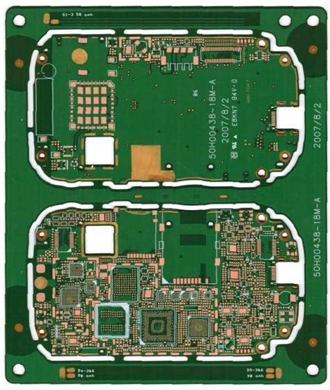
Maintaining signal integrity in drone flight controllers begins with strategic use of ground planes in your 4-layer PCB stackup. By placing a continuous ground layer adjacent to high-speed signal layers, you minimize electromagnetic interference (EMI) and reduce crosstalk between traces. This design approach ensures stable voltage reference points, which is critical for precise sensor data transmission and motor control signals.
When collaborating with PCB manufacturing companies, verify their capability to implement impedance-controlled routing and symmetrical layer stacking. Reputable suppliers like JHYPCB often recommend dedicating Layer 2 as a solid ground plane, sandwiched between power and signal layers, to optimize noise suppression. This configuration not only enhances performance but also aligns with cost-efficient PCB manufacturing business practices by reducing post-production debugging.
Balancing PCB manufacturing cost with quality requires careful material selection. For instance, using a 0.8mm to 1.6mm board thickness ensures adequate isolation between layers without overcomplicating fabrication. Always confirm dielectric constants and copper weights with your manufacturer to avoid impedance mismatches that degrade signal fidelity. By prioritizing ground plane integrity early in the design phase, you streamline production timelines and ensure reliable operation in high-vibration drone environments.
PCB Thickness Manufacturer Guidelines
When designing a 4-layer PCB for drone flight controllers, adhering to PCB manufacturing guidelines for thickness ensures reliability and performance. Most PCB manufacturing companies recommend a standard thickness of 1.6mm for drone applications, balancing structural rigidity and space constraints. However, specific use cases may require thinner (1.0mm) or thicker (2.0mm) profiles—choices influenced by thermal management needs, impedance control, and component density.
Thinner boards reduce PCB manufacturing cost by using less material but may compromise durability in high-vibration environments. Conversely, thicker stackups improve heat dissipation and signal integrity, critical for high-speed circuits in flight controllers. Always consult your manufacturer’s design rules to align layer arrangement with their fabrication capabilities. For instance, core/prepreg material choices directly affect dielectric consistency, which impacts impedance matching—a key factor in minimizing signal loss.
Balancing these considerations requires understanding how PCB manufacturing business models operate. Reputable suppliers optimize processes to maintain tight tolerances (±10%) on thickness, ensuring consistency across batches. Prioritize vendors with aerospace-grade certifications, as drone PCBs demand precision to withstand operational stressors while keeping production timelines and costs predictable.
High-Speed Drone PCB Routing
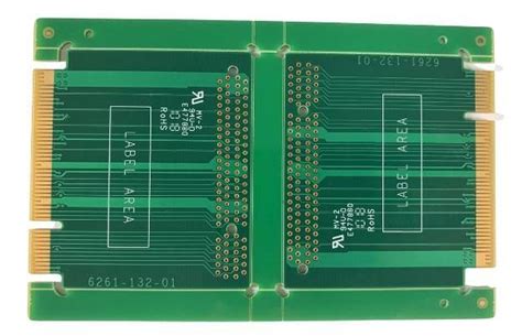
When designing PCB manufacturing solutions for high-speed drone flight controllers, routing precision directly impacts signal integrity and electromagnetic interference (EMI) performance. You’ll need to prioritize controlled impedance traces for critical signals like PWM outputs and sensor interfaces, ensuring minimal crosstalk between adjacent layers. Differential pair routing becomes essential for high-frequency communication protocols (e.g., SPI, I2C), with spacing rules dictated by your chosen PCB manufacturing companies to avoid signal degradation.
A 20°45° angle routing approach reduces reflections in high-speed circuits, while via stitching along ground planes maintains consistent return paths. For compact designs, microvias from advanced PCB manufacturing business partners enable vertical interconnects without sacrificing layer space. However, balancing PCB manufacturing cost with performance requires careful planning—thinner dielectrics improve signal speed but may increase production complexity.
Always consult your manufacturer’s design rules for trace width/spacing tolerances, especially when operating above 1 GHz. Pairing a solid ground plane (Layer 2) with split power planes (Layer 3) minimizes noise coupling, while embedded decoupling capacitors near ICs further stabilize high-speed power delivery. Transitioning between layers? Use back-drilled vias to eliminate stub effects—a technique increasingly adopted by leading PCB manufacturing specialists for aerospace-grade drone controllers.
STM32F4 PCB Layer Integration
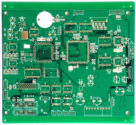
When integrating STM32F4 microcontrollers into your drone flight controller design, PCB manufacturing strategies directly influence performance and reliability. For optimal operation, dedicate specific layers to signal routing, power distribution, and ground planes. Position high-speed signals (like clock lines or USB interfaces) on inner layers adjacent to ground planes to minimize EMI—a critical factor in compact drone systems.
PCB manufacturing companies often recommend allocating a full layer for the microcontroller’s power rails (3.3V, 5V) to ensure stable voltage delivery, especially during rapid throttle changes. Use via-in-pad techniques for the STM32F4’s BGA package to reduce inductance in power paths, but verify alignment with your manufacturer’s capabilities to avoid increasing PCB manufacturing cost.
Thermal management is equally vital: integrate thermal vias under the MCU’s exposed pad and connect them to internal ground planes for heat dissipation. When collaborating with PCB manufacturing business partners, confirm dielectric materials (e.g., FR-4 with high Tg) and copper weights that balance thermal performance and weight constraints. Finally, cross-validate layer stackup parameters (e.g., 0.8mm–1.6mm total thickness) against your drone’s structural requirements to avoid mechanical conflicts during assembly.
Cost-Effective 4-Layer Stackups
When balancing performance and PCB manufacturing cost, your drone flight controller’s stackup design must prioritize both electrical efficiency and budget constraints. Start by selecting cost-optimized materials—standard FR-4 substrates with mid-range glass transition temperatures (Tg) often strike a balance between thermal stability and affordability. For PCB manufacturing companies, a symmetrical layer arrangement (e.g., Signal-Ground-Power-Signal) minimizes warpage risks while maintaining consistent impedance control, reducing post-production rework.
To further lower PCB manufacturing business expenses, consider using 1 oz copper for inner layers and 0.5 oz for outer layers—this reduces material usage without compromising current-carrying capacity. Prepreg thickness choices also matter: thinner dielectrics between power and ground planes improve decoupling but may raise costs. Work with suppliers to identify standardized prepreg combinations that align with your design’s EMI and thermal needs.
Reputable PCB manufacturing partners often offer panelization services to maximize material yield, effectively lowering per-unit costs for bulk orders. Avoid over-engineering trace widths or via counts; adhering to manufacturer-recommended design rules ensures reliability while keeping fabrication steps simple. By integrating these strategies, you achieve a stackup that meets drone controller demands without inflating budgets—proving that smart design and supplier collaboration can optimize both performance and cost.
JHYPCB Drone Controller Standards
When selecting a partner for PCB manufacturing, it’s critical to align with companies that specialize in high-reliability designs for aerospace applications. JHYPCB, a leader among PCB manufacturing companies, adheres to stringent standards tailored for drone flight controllers, ensuring robust performance under dynamic operating conditions. Their 4-layer stackups prioritize signal isolation between power and control layers, minimizing electromagnetic interference (EMI) risks common in compact drone systems.
For cost-sensitive projects, balancing PCB manufacturing cost with quality requires precise material selection. JHYPCB’s stackups use FR-4 substrates with optimized dielectric constants, maintaining signal integrity while avoiding over-engineering. Their thermal management protocols ensure stable operation across temperature fluctuations, a non-negotiable for altitude-varying drone environments.
In the PCB manufacturing business, scalability and compliance are equally vital. JHYPCB’s production workflows integrate automated optical inspection (AOI) and impedance testing, guaranteeing consistency across batches—a necessity for mass-produced drone controllers. By following their thickness tolerances (typically 1.6mm ±10%), you avoid mechanical fit issues during assembly.
Ultimately, partnering with a manufacturer that understands high-speed routing constraints and ground plane optimization ensures your design meets both functional and regulatory benchmarks. This alignment reduces prototyping cycles, allowing faster time-to-market for next-gen drone systems.
Conclusion
When designing 4-layer PCBs for drone flight controllers, balancing performance and pcb manufacturing cost requires strategic planning. Collaborating with experienced pcb manufacturing companies ensures adherence to critical parameters like layer thickness and material selection, directly impacting signal integrity and thermal management. While optimizing pcb manufacturing business workflows, prioritize ground plane configurations and power routing to minimize electromagnetic interference—a non-negotiable for stable flight operations.
Reputable manufacturers often recommend 1.6mm board thickness as a baseline, though customization based on high-speed signal demands might justify adjustments. Always verify that your pcb manufacturing partner follows industry standards for impedance control and via placement, particularly for integrating components like the STM32F4 MCU. This alignment reduces prototyping iterations, ultimately lowering long-term production expenses.
Ultimately, the success of your drone’s flight controller hinges on how well your stackup design aligns with both electrical requirements and the technical capabilities of your chosen pcb manufacturing supplier. By prioritizing these factors, you ensure reliability without compromising on cost-efficiency or scalability.
FAQs
How does 4-layer stackup design affect drone controller reliability?
A well-optimized stackup ensures stable power delivery and minimizes signal interference. By separating PCB manufacturing layers for power, ground, and signals, you reduce noise and improve thermal management—critical for high-speed drone operations.
What factors influence PCB manufacturing cost for 4-layer designs?
Cost depends on material quality, copper weight, and tolerances. Working with experienced PCB manufacturing companies helps balance expenses—for example, selecting standard FR-4 substrates instead of high-frequency laminates can lower costs without sacrificing performance.
Can I use the same stackup for different drone models?
While core principles apply, variations in component density and signal speed may require adjustments. Always consult your PCB manufacturing business partner to validate layer arrangements for specific designs.
How do ground planes improve signal integrity?
Dedicated ground layers in a 4-layer PCB act as shields against electromagnetic interference (EMI). This setup is especially critical for flight controllers, where stable communication between sensors and processors is non-negotiable.
Why choose specialized suppliers for drone PCBs?
Drone controllers demand precision in impedance control and thermal stability. Reputable PCB manufacturing firms like JHYPCB adhere to aerospace-grade standards, ensuring your stackup meets rigorous environmental and electrical demands.
Ready to Optimize Your Drone PCB Design?
For expert guidance on 4-layer PCB stackups and manufacturer-recommended practices, please click here to connect with professionals who specialize in high-performance drone controller solutions.

