Programming PCB Boards: A Comprehensive Guide
Printed Circuit Boards (PCBs) are the backbone of modern electronics. They provide the physical platform for mounting and interconnecting electronic components, enabling the creation of complex circuits in a compact and efficient manner. However, designing and programming a PCB is a multi-faceted process that requires a deep understanding of electronics, software, and hardware integration. This article will explore the key steps involved in programming a PCB board, from design to implementation, and highlight best practices to ensure a successful project.
1. Understanding the Basics of PCB Design
Before diving into programming, it is essential to understand the fundamentals of PCB design. A PCB consists of multiple layers of conductive and insulating materials, with copper traces forming the electrical connections between components. The design process involves creating a schematic diagram, laying out the physical components, and routing the traces to ensure proper connectivity.
1.1 Schematic Design
The first step in PCB design is creating a schematic diagram. This is a symbolic representation of the circuit, showing how components are connected. Tools like KiCad, Eagle, or Altium Designer are commonly used for this purpose. The schematic serves as a blueprint for the PCB layout and helps identify potential issues early in the design process.
1.2 Component Placement
Once the schematic is complete, the next step is to place the components on the PCB. This involves arranging components in a way that minimizes trace lengths, reduces electromagnetic interference (EMI), and ensures efficient heat dissipation. Proper component placement is critical for the performance and reliability of the final product.
1.3 Routing
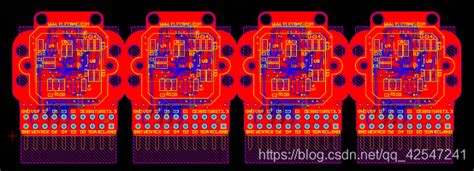
Routing is the process of creating the copper traces that connect the components. This step requires careful planning to avoid signal integrity issues, such as crosstalk or impedance mismatches. Modern PCB design software often includes auto-routing features, but manual routing is still necessary for complex or high-speed designs.
2. Integrating Microcontrollers and Programmable Logic
Most modern PCBs include microcontrollers or programmable logic devices (PLDs) that require programming to function. These devices act as the “brain” of the circuit, executing software instructions to control the behavior of the system.
2.1 Choosing the Right Microcontroller
Selecting the appropriate microcontroller is a critical decision in PCB design. Factors to consider include processing power, memory, input/output (I/O) pins, and power consumption. Popular choices include the Arduino series, STM32, and ESP32 for embedded systems, and FPGAs for more complex applications.
2.2 Writing Firmware
Firmware is the software that runs on the microcontroller. It is typically written in C or C++, although other languages like Python (for microcontrollers like the Raspberry Pi Pico) may also be used. The firmware defines how the microcontroller interacts with other components on the PCB, such as sensors, actuators, and communication modules.
2.3 Debugging and Testing
Debugging is an essential part of firmware development. Tools like JTAG debuggers, logic analyzers, and serial monitors can help identify and fix issues in the code. Testing should be done incrementally, starting with individual components and gradually integrating them into the full system.
3. Programming the PCB
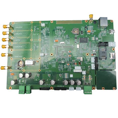
Once the PCB is designed and the firmware is written, the next step is to program the microcontroller or PLD. This involves transferring the firmware from a development environment to the target device.
3.1 Programming Interfaces
There are several ways to program a microcontroller, depending on the device and the development environment. Common interfaces include:
- In-System Programming (ISP): This method allows the microcontroller to be programmed while it is mounted on the PCB. It typically uses a serial interface like SPI or I2C.
- JTAG: Joint Test Action Group (JTAG) is a standard interface for programming and debugging microcontrollers and FPGAs.
- Bootloaders: Some microcontrollers come with a bootloader pre-installed, allowing them to be programmed via a USB or UART connection.
3.2 Using Development Tools
Most microcontroller manufacturers provide development tools and software to facilitate programming. For example, the Arduino IDE is widely used for programming Arduino boards, while STM32CubeIDE is tailored for STM32 microcontrollers. These tools often include libraries and example code to simplify the development process.
3.3 Firmware Updates
In many applications, it is important to have the ability to update the firmware after the PCB has been deployed. This can be done over-the-air (OTA) using wireless communication modules like Wi-Fi or Bluetooth, or through a wired connection like USB.
4. Ensuring Signal Integrity and Power Management
Signal integrity and power management are critical considerations in PCB design and programming. Poor signal integrity can lead to data corruption, while inadequate power management can cause the system to fail.
4.1 Signal Integrity
Signal integrity refers to the quality of the electrical signals traveling through the PCB. Factors that affect signal integrity include trace impedance, crosstalk, and electromagnetic interference (EMI). Techniques to improve signal integrity include:
- Using proper trace widths and spacing.
- Adding ground planes to reduce noise.
- Implementing differential signaling for high-speed data transmission.
4.2 Power Management
Power management involves ensuring that all components on the PCB receive the correct voltage and current. This may require the use of voltage regulators, power converters, and decoupling capacitors. Power consumption should also be optimized, especially for battery-powered devices.
5. Testing and Validation
Testing is a crucial step in the PCB programming process. It ensures that the board functions as intended and meets all design requirements.
5.1 Functional Testing
Functional testing involves verifying that the PCB performs its intended functions. This may include testing individual components, as well as the system as a whole. Automated test equipment (ATE) can be used to streamline this process.
5.2 Environmental Testing
Environmental testing evaluates the PCB’s performance under various conditions, such as temperature extremes, humidity, and vibration. This is particularly important for industrial or automotive applications.
5.3 Compliance Testing
Compliance testing ensures that the PCB meets relevant industry standards and regulations, such as FCC certification for electromagnetic compatibility (EMC) or RoHS compliance for environmental safety.
6. Best Practices for PCB Programming
To ensure a successful PCB programming project, consider the following best practices:
6.1 Plan Ahead
Careful planning is essential for avoiding costly mistakes. This includes creating a detailed schematic, selecting the right components, and defining clear requirements for the firmware.
6.2 Use Version Control
Version control systems like Git can help manage changes to the firmware and PCB design files. This is especially important for collaborative projects.
6.3 Document Everything
Documentation is key to maintaining and troubleshooting the PCB. This includes schematics, bill of materials (BOM), firmware code, and test results.
6.4 Iterate and Improve
PCB design and programming is an iterative process. Be prepared to make multiple revisions and learn from each iteration to improve the final product.
7. Future Trends in PCB Programming
As technology continues to evolve, so do the tools and techniques for PCB programming. Some emerging trends include:
7.1 AI-Assisted Design
Artificial intelligence (AI) is being used to automate aspects of PCB design, such as component placement and routing. This can significantly reduce development time and improve design quality.
7.2 IoT Integration
The Internet of Things (IoT) is driving demand for PCBs with wireless connectivity and low power consumption. This requires new approaches to firmware development and power management.
7.3 3D Printing
3D printing is being explored as a way to create custom PCBs quickly and cost-effectively. This could revolutionize prototyping and small-scale production.
Conclusion
Programming a PCB board is a complex but rewarding process that combines elements of electronics, software, and hardware design. By following best practices and staying up-to-date with emerging trends, engineers can create innovative and reliable PCBs that power the next generation of electronic devices. Whether you’re a beginner or an experienced professional, mastering the art of PCB programming is an essential skill in the world of modern electronics.

