How to Identify PCB Components
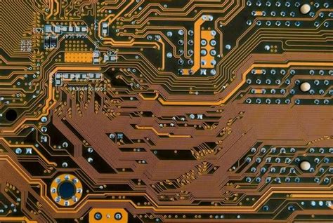
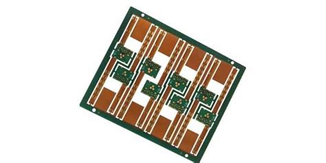
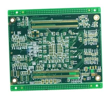
Printed Circuit Boards (PCBs) are the backbone of modern electronics. They are used in almost every electronic device, from smartphones and computers to industrial machinery and medical equipment. A PCB is a flat board made of insulating material, such as fiberglass, with conductive pathways etched or printed onto its surface. These pathways connect various electronic components, such as resistors, capacitors, integrated circuits (ICs), and connectors, to form a functional electronic circuit.
Identifying PCB components is a crucial skill for anyone involved in electronics, whether you are a hobbyist, a technician, or an engineer. Properly identifying components allows you to troubleshoot, repair, or modify a PCB effectively. This article will guide you through the process of identifying PCB components, covering the most common types of components, their characteristics, and the tools and techniques used for identification.
1. Understanding the Basics of PCB Components
Before diving into the identification process, it is essential to understand the basic types of components found on a PCB. These components can be broadly categorized into two groups: active components and passive components.
1.1 Active Components
Active components are electronic devices that can control the flow of electricity. They require an external power source to operate and can amplify, switch, or modify electrical signals. Common active components include:
- Integrated Circuits (ICs): These are complex components that contain multiple electronic circuits within a single package. ICs can perform a wide range of functions, from simple logic operations to complex signal processing.
- Transistors: Transistors are semiconductor devices used to amplify or switch electronic signals. They come in various types, such as bipolar junction transistors (BJTs) and field-effect transistors (FETs).
- Diodes: Diodes are semiconductor devices that allow current to flow in only one direction. They are commonly used for rectification, signal demodulation, and voltage regulation.
- Operational Amplifiers (Op-Amps): Op-amps are high-gain voltage amplifiers used in a variety of analog circuits, such as filters, oscillators, and comparators.
1.2 Passive Components
Passive components do not require an external power source to operate and do not amplify or modify electrical signals. Instead, they store, dissipate, or control the flow of electricity. Common passive components include:
- Resistors: Resistors are used to limit the flow of current in a circuit. They are characterized by their resistance value, measured in ohms (Ω).
- Capacitors: Capacitors store electrical energy in an electric field. They are used for filtering, coupling, and energy storage. Capacitance is measured in farads (F).
- Inductors: Inductors store energy in a magnetic field when electrical current passes through them. They are used in filters, oscillators, and power supplies. Inductance is measured in henries (H).
- Transformers: Transformers are used to transfer electrical energy between two or more circuits through electromagnetic induction. They are commonly used to step up or step down voltage levels.
2. Tools for Identifying PCB Components
To identify PCB components effectively, you will need a set of tools that can help you inspect, measure, and analyze the components. Some of the most commonly used tools include:
2.1 Magnifying Glass or Microscope
A magnifying glass or a microscope is essential for inspecting small components and reading their markings. Many PCB components, especially surface-mount devices (SMDs), have tiny labels that can be difficult to read with the naked eye.
2.2 Multimeter
A multimeter is a versatile tool that can measure voltage, current, and resistance. It is particularly useful for testing resistors, capacitors, and diodes. Some advanced multimeters can also measure capacitance and inductance.
2.3 Component Tester
A component tester, also known as an LCR meter, can measure the inductance (L), capacitance (C), and resistance (R) of components. Some component testers can also identify the type of component and its value automatically.
2.4 Oscilloscope
An oscilloscope is used to visualize electrical signals in a circuit. It is particularly useful for analyzing the behavior of active components, such as transistors and ICs, by observing their input and output waveforms.
2.5 Datasheets and Reference Guides
Datasheets and reference guides provide detailed information about the specifications, pin configurations, and typical applications of electronic components. They are invaluable resources for identifying and understanding the function of components on a PCB.
3. Techniques for Identifying PCB Components
Now that you have the necessary tools, let’s explore the techniques for identifying different types of PCB components.
3.1 Identifying Resistors
Resistors are one of the most common components on a PCB. They are typically marked with colored bands that indicate their resistance value and tolerance. The color code for resistors is standardized, and you can use a resistor color code chart to decode the value.
- Through-Hole Resistors: These resistors have leads that go through holes in the PCB. They are usually marked with colored bands.
- Surface-Mount Resistors (SMD Resistors): SMD resistors are smaller and have no leads. They are marked with a numerical code that indicates their resistance value. For example, a resistor marked “103” has a resistance of 10,000 ohms (10 kΩ).
3.2 Identifying Capacitors
Capacitors come in various shapes and sizes, and their identification can be more challenging than resistors.
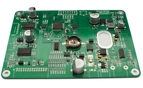
- Electrolytic Capacitors: These capacitors are polarized, meaning they have a positive and a negative terminal. They are usually cylindrical and marked with their capacitance value and voltage rating. The negative terminal is often marked with a stripe or a minus sign.
- Ceramic Capacitors: Ceramic capacitors are non-polarized and often small and disc-shaped. They are marked with a numerical code that indicates their capacitance value. For example, a capacitor marked “104” has a capacitance of 100,000 picofarads (100 nF).
- Tantalum Capacitors: Tantalum capacitors are also polarized and have a distinctive rectangular shape. They are marked with their capacitance value and voltage rating.
3.3 Identifying Inductors
Inductors are less common than resistors and capacitors, but they are still important components in many circuits.
- Through-Hole Inductors: These inductors have leads and are often wound with wire around a core. They may be marked with their inductance value, but this is not always the case.
- Surface-Mount Inductors (SMD Inductors): SMD inductors are small and may be marked with a numerical code that indicates their inductance value. However, like through-hole inductors, they may not always be marked.
3.4 Identifying Diodes
Diodes are polarized components that allow current to flow in only one direction. They are usually marked with a stripe or a band that indicates the cathode (negative) terminal.
- Through-Hole Diodes: These diodes have leads and are often marked with a stripe near the cathode terminal.
- Surface-Mount Diodes (SMD Diodes): SMD diodes are small and may be marked with a stripe or a dot near the cathode terminal.
3.5 Identifying Transistors
Transistors are three-terminal devices that can amplify or switch electronic signals. They come in various packages, such as TO-92, TO-220, and SOT-23.
- Bipolar Junction Transistors (BJTs): BJTs have three terminals: the emitter, base, and collector. The pin configuration varies depending on the transistor type (NPN or PNP) and package.
- Field-Effect Transistors (FETs): FETs also have three terminals: the source, gate, and drain. Like BJTs, the pin configuration varies depending on the transistor type (N-channel or P-channel) and package.
3.6 Identifying Integrated Circuits (ICs)
ICs are complex components that can contain thousands or even millions of transistors. They are usually marked with a part number that can be used to look up their datasheet.
- Through-Hole ICs: These ICs have leads that go through holes in the PCB. They are often in a dual in-line package (DIP) and are marked with a part number.
- Surface-Mount ICs (SMD ICs): SMD ICs are smaller and have no leads. They are often in a small outline package (SOP) or quad flat package (QFP) and are marked with a part number.
3.7 Identifying Connectors and Headers
Connectors and headers are used to connect the PCB to external devices or other PCBs. They come in various shapes and sizes, and their identification often involves matching the physical characteristics to a known type.
- Pin Headers: These are rows of pins that can be used to connect wires or other PCBs. They are often marked with the number of pins (e.g., “2×5” for a 10-pin header).
- USB Connectors: USB connectors are used to connect USB devices to the PCB. They are usually marked with the USB logo.
- Power Connectors: Power connectors are used to supply power to the PCB. They are often marked with the voltage and current ratings.
4. Practical Tips for Identifying PCB Components
- Use a Reference Designator: PCBs are often labeled with reference designators (e.g., R1, C2, U3) that indicate the type of component and its position on the board. These designators can help you locate and identify components more easily.
- Check the PCB Silkscreen: The silkscreen is the layer of text and symbols printed on the PCB. It often includes component labels, polarity markings, and other useful information.
- Consult the Schematic: If you have access to the PCB schematic, it can be a valuable resource for identifying components and understanding their connections.
- Look for Markings: Many components are marked with their part number, value, or other identifying information. Use a magnifying glass or microscope to read these markings.
- Test the Component: If you are unsure about a component’s identity, you can use a multimeter or component tester to measure its electrical properties and compare them to known values.
5. Conclusion
Identifying PCB components is a fundamental skill for anyone working with electronics. By understanding the basic types of components, using the right tools, and applying the techniques described in this article, you can confidently identify and work with the components on a PCB. Whether you are troubleshooting a faulty circuit, repairing a damaged device, or designing your own PCB, the ability to identify components is essential for success in the world of electronics.

