The Best Temperature to Solder Electronics: A Comprehensive Guide
Soldering is a fundamental skill in electronics, essential for creating reliable electrical connections between components. Whether you’re a hobbyist working on a DIY project or a professional assembling complex circuits, understanding the best temperature to solder electronics is crucial for achieving strong, durable, and defect-free joints. This article explores the factors that influence soldering temperature, the ideal temperature ranges for different types of soldering, and tips for optimizing your soldering process.
1. Understanding Soldering Basics
Soldering involves melting a filler metal (solder) to join two or more metal surfaces. The solder acts as a conductive adhesive, forming a bond as it cools and solidifies. The process requires precise control of heat to ensure the solder flows properly without damaging the components or the circuit board.
The two most common types of soldering in electronics are:
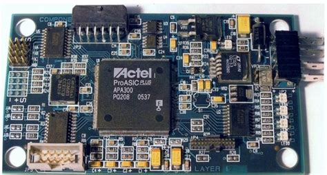
- Through-Hole Soldering: Used for components with leads that pass through holes in a printed circuit board (PCB).
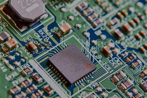
- Surface-Mount Soldering: Used for smaller components that sit directly on the surface of a PCB.
Both methods require careful temperature management to avoid issues like cold joints, component damage, or lifted pads.
2. Factors Influencing Soldering Temperature
The ideal soldering temperature depends on several factors, including:
a. Type of Solder
The composition of the solder alloy determines its melting point. The most common solder alloys used in electronics are:
- Tin-Lead (Sn-Pb) Solder: Traditionally used in electronics, this alloy typically contains 60% tin and 40% lead (60/40). It has a melting point of around 183°C (361°F) and is known for its ease of use and reliability.
- Lead-Free Solder: Due to environmental and health concerns, lead-free solders have become more popular. These alloys often contain tin, silver, and copper (e.g., SAC305: 96.5% tin, 3% silver, 0.5% copper) and have higher melting points, typically around 217°C (422°F).
b. Component Sensitivity
Electronic components vary in their heat tolerance. Delicate components, such as integrated circuits (ICs) or surface-mount devices (SMDs), can be damaged by excessive heat. On the other hand, larger components like connectors or through-hole resistors can withstand higher temperatures.
c. PCB Material
The material of the PCB also plays a role. Standard FR-4 PCBs can tolerate temperatures up to 130-140°C (266-284°F) before they start to degrade. Prolonged exposure to high temperatures can cause warping or delamination of the board.
d. Soldering Method
The method of soldering—whether using a soldering iron, hot air rework station, or reflow oven—affects the temperature requirements. For example, reflow soldering typically involves a temperature profile with multiple stages, while hand soldering with an iron requires a more straightforward approach.

3. Ideal Temperature Ranges for Soldering
a. Hand Soldering with a Soldering Iron
For hand soldering, the temperature of the soldering iron tip is critical. Here are some general guidelines:
- Tin-Lead Solder: Set the soldering iron temperature between 315°C and 370°C (600°F and 700°F). This range ensures the solder melts quickly and flows smoothly without overheating the components.
- Lead-Free Solder: Due to its higher melting point, lead-free solder requires a higher temperature, typically between 340°C and 380°C (650°F and 715°F).
It’s important to note that the actual temperature at the joint may be lower than the iron’s tip temperature, especially if the tip is not making good contact with the joint.
b. Reflow Soldering
Reflow soldering is commonly used for surface-mount components and involves heating the entire PCB in a controlled manner. The temperature profile for reflow soldering typically includes four stages:
- Preheat: Gradually raise the temperature to activate the flux and remove moisture (typically 1-3°C per second).
- Soak: Hold the temperature just below the solder’s melting point to ensure even heating (e.g., 150-180°C for tin-lead solder or 180-200°C for lead-free solder).
- Reflow: Raise the temperature above the solder’s melting point to form the joints (e.g., 183°C for tin-lead solder or 217°C for lead-free solder).
- Cooling: Gradually cool the board to solidify the solder and prevent thermal shock.
c. Hot Air Rework
Hot air rework stations are used for repairing or replacing components. The temperature settings depend on the component size and the type of solder:
- Small Components: Use a lower temperature (e.g., 300-350°C or 570-660°F) to avoid damaging the component or the PCB.
- Larger Components: Higher temperatures (e.g., 350-400°C or 660-750°F) may be necessary to ensure the solder melts evenly.
4. Common Soldering Problems and Temperature-Related Solutions
a. Cold Joints
Cold joints occur when the solder does not melt completely, resulting in a weak, grainy connection. This is often caused by insufficient heat. To fix this, increase the soldering iron temperature or ensure the tip is in full contact with the joint.
b. Component Damage
Overheating can damage sensitive components or the PCB. To prevent this, use the lowest effective temperature and minimize the time the iron is in contact with the joint.
c. Solder Bridges
Solder bridges occur when excess solder creates a short circuit between adjacent pins. This can happen if the temperature is too high, causing the solder to flow uncontrollably. Reduce the temperature and use a solder wick or desoldering pump to remove excess solder.
d. Lifted Pads
Lifted pads are caused by excessive heat or mechanical stress. To avoid this, use a temperature appropriate for the PCB material and handle the board gently during soldering.
5. Tips for Optimizing Soldering Temperature
- Use a Temperature-Controlled Soldering Iron: A soldering iron with adjustable temperature settings allows you to fine-tune the heat for different tasks.
- Select the Right Tip: The size and shape of the soldering iron tip affect heat transfer. Use a tip that matches the size of the joint for optimal results.
- Preheat the PCB: For large or complex boards, preheating the PCB can help reduce thermal stress and improve solder flow.
- Monitor the Joint: Watch the solder as it melts and flows. If it takes too long to melt, increase the temperature slightly. If it flows too quickly or spatters, reduce the temperature.
- Use Flux: Flux helps the solder flow and adhere to the joint. It also reduces the need for excessive heat.
6. Conclusion
The best temperature to solder electronics depends on the type of solder, the components being soldered, and the soldering method. For hand soldering, a temperature range of 315-380°C (600-715°F) is generally suitable, with lower temperatures for tin-lead solder and higher temperatures for lead-free solder. Reflow soldering and hot air rework require more precise temperature profiles to ensure even heating and avoid damage.
By understanding the factors that influence soldering temperature and following best practices, you can achieve reliable, high-quality solder joints that stand the test of time. Whether you’re a beginner or an experienced technician, mastering temperature control is key to successful soldering in electronics.

