PCB Short Circuit Repair Methods: A Comprehensive Guide
Printed Circuit Boards (PCBs) are the backbone of modern electronics, found in everything from consumer gadgets to industrial machinery. However, one of the most common and frustrating issues in PCB manufacturing and repair is the short circuit. A short circuit occurs when an unintended electrical connection forms between two points in a circuit, leading to malfunction, overheating, or even permanent damage.
Detecting and repairing PCB short circuits requires a systematic approach, combining visual inspection, testing techniques, and precise repair methods. This article explores the causes of PCB short circuits, detection methods, and effective repair techniques.
1. Causes of PCB Short Circuits
Understanding the root causes of PCB short circuits helps in prevention and efficient troubleshooting. Common causes include:
1.1. Solder Bridges
- Excess solder between adjacent pads or traces can create an unintended connection.
- Common in fine-pitch components like QFPs (Quad Flat Packages) and BGAs (Ball Grid Arrays).
1.2. Copper Traces Too Close Together
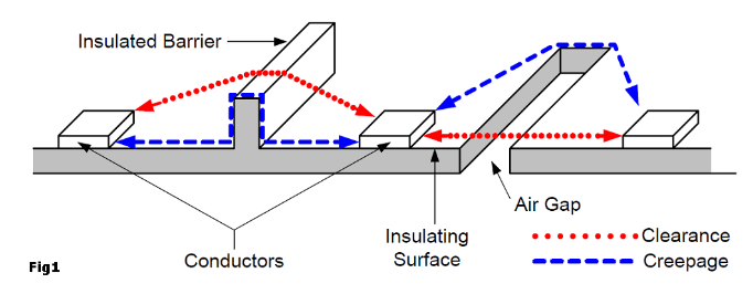
- Poor PCB design with insufficient clearance between traces increases short-circuit risks.
- Acid traps (narrow gaps in copper) can lead to etching errors, causing shorts.
1.3. Component Misplacement or Damage
- Incorrectly placed components (e.g., capacitors, resistors) can bridge connections.
- Damaged components (cracked ICs, broken leads) may cause internal shorts.
1.4. Conductive Debris or Contamination
- Metal shavings, solder splashes, or dust can create unintended conductive paths.
- Moisture or chemical residues may lead to corrosion-induced shorts.
1.5. Manufacturing Defects
- Poor etching, incomplete solder mask application, or plating errors can cause hidden shorts.
- Vias or through-holes with excessive copper may create internal shorts.
2. Detecting PCB Short Circuits
Before repairing a short circuit, it must be accurately located. Several techniques are used:
2.1. Visual Inspection
- Magnification Tools: Use a magnifying glass or microscope to inspect solder joints and traces.
- Bright Lighting: Helps identify solder bridges, damaged traces, or foreign debris.
2.2. Multimeter Testing
- Continuity Mode: A multimeter in continuity mode beeps when a short is detected.
- Resistance Measurement: A near-zero resistance between two points indicates a short.
2.3. Thermal Imaging (Infrared Cameras)
- Short circuits often generate heat. An IR camera can detect hot spots.
- Useful for finding hidden shorts in multilayer PCBs.
2.4. Short Circuit Tracer / Current Injection Method
- Inject a low current (using a bench power supply) and track voltage drops.
- A thermal camera or alcohol evaporation technique can locate the short.
2.5. Flying Probe and Automated Optical Inspection (AOI)
- Automated testers in PCB manufacturing can detect shorts before assembly.
- AOI systems scan for solder defects and misalignments.

3. PCB Short Circuit Repair Methods
Once a short is detected, the appropriate repair method depends on the cause and location.
3.1. Removing Solder Bridges
- Desoldering Braid/Wick: Place the braid over the excess solder and heat with a soldering iron to absorb the solder.
- Solder Sucker: A vacuum tool removes molten solder quickly.
- Fine-Tip Soldering Iron: Carefully reflow and remove excess solder.
3.2. Trace Repair (Cutting and Jumpering)
- Isolating the Short: Use a sharp blade or fiberglass pen to cut the shorted trace.
- Bypassing with Jumper Wires: Solder a thin insulated wire to reconnect the circuit.
3.3. Component Replacement
- Desoldering and Resoldering: Remove the faulty component and replace it.
- Hot Air Rework Station: Useful for SMD components (e.g., BGAs, QFNs).
3.4. Conductive Debris Removal
- Isopropyl Alcohol (IPA) Cleaning: Removes flux residues and conductive contaminants.
- Compressed Air or Brush: Clears metal particles and dust.
3.5. PCB Layer Separation (For Multilayer Shorts)
- If a short exists between internal layers, localized heating or drilling may be required.
- In severe cases, the PCB may need replacement.
3.6. Solder Mask Reapplication
- Apply UV-curable solder mask to exposed copper areas to prevent future shorts.
4. Preventing PCB Short Circuits
Prevention is better than repair. Key strategies include:
4.1. Proper PCB Design Practices
- Maintain adequate trace spacing (follow IPC-2221 standards).
- Avoid sharp angles in traces to prevent acid traps.
4.2. Controlled Soldering Process
- Use the right solder amount and temperature.
- Implement reflow profile optimization for SMD components.
4.3. Regular Inspection and Testing
- Use AOI and flying probe tests in production.
- Perform in-circuit testing (ICT) for assembled boards.
4.4. Clean Working Environment
- Prevent contamination by keeping the workspace dust-free.
- Use ESD-safe tools to avoid static damage.
5. Conclusion
PCB short circuits can disrupt functionality and lead to costly failures, but with the right detection and repair methods, they can be efficiently resolved. Techniques such as visual inspection, multimeter testing, thermal imaging, and current injection help locate shorts, while solder removal, trace repair, and component replacement provide effective fixes.
By following preventive measures like proper PCB design, controlled soldering, and regular testing, manufacturers and repair technicians can minimize the occurrence of short circuits, ensuring reliable and long-lasting electronic devices.
For complex multilayer PCB shorts, professional repair services may be necessary. However, with the right tools and knowledge, most short circuits can be successfully repaired, restoring the PCB to full functionality.
Final Thoughts
Understanding PCB short circuits is essential for electronics engineers, technicians, and hobbyists. By mastering detection and repair techniques, you can save time, reduce costs, and improve the reliability of electronic assemblies. Whether you’re troubleshooting a simple solder bridge or a hidden internal short, a methodical approach ensures successful repairs.
Would you like additional details on any specific repair method? Let me know how I can assist further!


