Eagle PCB: A Comprehensive Guide to PCB Design and Layout
Introduction to Eagle PCB
Eagle (Easily Applicable Graphical Layout Editor) PCB is one of the most popular printed circuit board (PCB) design software tools used by engineers, hobbyists, and professionals worldwide. Developed by CadSoft Computer and now owned by Autodesk, Eagle has established itself as a go-to solution for PCB design due to its powerful features, user-friendly interface, and extensive component libraries.
Since its initial release in 1988, Eagle PCB has evolved significantly, transitioning from a simple schematic capture tool to a comprehensive PCB design suite capable of handling complex multilayer boards. Its widespread adoption can be attributed to several factors: the availability of a free version for non-commercial use, cross-platform compatibility (Windows, Linux, and macOS), and a large community of users who contribute libraries and share knowledge.
Key Features of Eagle PCB
1. Schematic Editor
The schematic editor in Eagle PCB provides an intuitive environment for creating circuit diagrams. Key features include:
- Hierarchical schematic design for complex projects
- Real-time electrical rule checking (ERC)
- Easy component placement and connection
- Support for custom symbols and footprints
- Netlist generation for PCB layout
The schematic editor uses a grid-based approach where components can be placed and connected using nets. The interface allows for easy navigation between different sheets in hierarchical designs, making it suitable for both simple and complex projects.
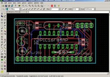
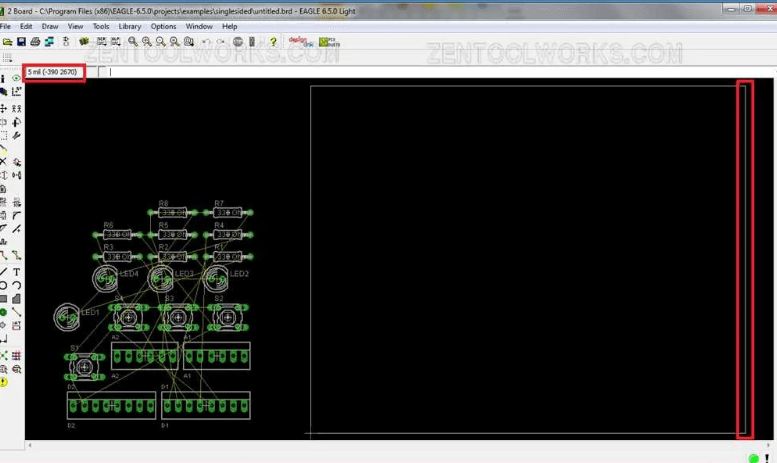
2. Board Layout Editor
The board layout editor is where the physical PCB takes shape. Notable features include:
- Support for up to 16 signal layers (in professional version)
- Comprehensive design rule checking (DRC)
- Autorouter functionality (with limitations)
- 3D board visualization
- Copper pour and polygon management
- Measurement tools for precise component placement
The layout editor provides a realistic representation of the final PCB, allowing designers to optimize component placement and routing for manufacturability and performance.
3. Component Libraries
Eagle comes with an extensive collection of pre-made components, and users can:
- Access thousands of ready-to-use components
- Create custom components with the library editor
- Import community-created libraries
- Manage personal libraries efficiently
The library system is one of Eagle’s strengths, with many manufacturers providing Eagle-compatible footprints and symbols for their components.
4. Design Rule Checking
Eagle’s DRC (Design Rule Checking) feature helps prevent manufacturing issues by:
- Verifying minimum trace widths and spacings
- Checking hole sizes and annular rings
- Validating solder mask and silkscreen requirements
- Ensuring proper clearances between objects
Designers can customize DRC settings to match their manufacturer’s capabilities, reducing the risk of board failures.
Workflow in Eagle PCB
1. Project Setup
Creating a new project in Eagle involves:
- Defining project parameters and design rules
- Setting up the schematic and board files
- Configuring layers and grid settings
- Establishing the design environment preferences
Proper setup at this stage ensures smoother workflow throughout the design process.
2. Schematic Design
The schematic design process includes:
- Placing components from libraries
- Connecting components with nets
- Assigning values and part numbers
- Organizing the schematic for readability
- Running ERC to identify potential issues
A well-designed schematic serves as the foundation for an effective PCB layout.
3. Board Layout
Transitioning from schematic to board layout involves:
- Initial component placement considering:
- Mechanical constraints
- Thermal management
- Signal integrity
- Manufacturing requirements
- Routing traces while adhering to:
- Electrical requirements
- High-speed design rules
- EMI/EMC considerations
- Adding copper pours for power and ground
- Finalizing silkscreen and solder mask layers
4. Verification and Output
Before generating manufacturing files, designers must:
- Run comprehensive DRC checks
- Verify netlist consistency
- Inspect the board in 3D view
- Generate Gerber files, drill files, and BOM
- Create assembly drawings if required
Advanced Features
1. User Language Programs (ULPs)
Eagle’s ULP system allows for:
- Automation of repetitive tasks
- Custom report generation
- Specialized export formats
- Enhanced functionality through scripts
Many third-party ULPs are available to extend Eagle’s capabilities.
2. 3D Visualization
The 3D viewer enables:
- Realistic preview of the final PCB
- Mechanical integration checks
- Component height verification
- Export for use in mechanical CAD software
3. Version Control Integration
Eagle supports:
- Native integration with version control systems
- Design history tracking
- Team collaboration features
- Change management capabilities
Advantages of Using Eagle PCB
1. Accessibility
- Free version available for non-commercial use
- Low-cost commercial licenses compared to enterprise tools
- Available on multiple platforms
2. Community Support
- Large user base for troubleshooting
- Abundance of online tutorials and resources
- Active forums and user groups
- Extensive third-party library contributions
3. Scalability
- Suitable for simple to moderately complex designs
- Handles both through-hole and SMD components
- Supports high-speed design techniques
- Capable of RF and mixed-signal layouts
4. Industry Standard
- Widely recognized in the electronics industry
- Accepted by most PCB manufacturers
- Compatible with many CAM tools
- Integration with other Autodesk products
Limitations and Considerations
While Eagle is powerful, it has some limitations:
- The free version restricts board size and layers
- The autorouter is basic compared to high-end tools
- Complex high-speed designs may require additional verification
- Large component libraries can become unwieldy
- Steeper learning curve for advanced features
Eagle PCB in the Professional Environment
In professional settings, Eagle is often used for:
- Rapid prototyping and proof-of-concept designs
- Small to medium volume production runs
- Educational purposes in engineering programs
- Hobbyist and maker projects transitioning to commercial products
Many companies use Eagle alongside more advanced tools, leveraging its ease of use for initial designs before transferring to enterprise systems for complex layouts.
Comparison with Other PCB Tools
Compared to alternatives like KiCad, Altium Designer, or OrCAD, Eagle:
- Strikes a balance between capability and complexity
- Offers better library management than some open-source options
- Lacks some advanced features of high-end commercial tools
- Provides more affordable licensing options
- Maintains strong file compatibility across versions
Future of Eagle PCB
Under Autodesk’s ownership, Eagle has seen:
- Improved integration with other Autodesk products
- Enhanced cloud collaboration features
- Regular updates and feature additions
- Better support for modern design requirements
The software continues to evolve while maintaining its core usability that made it popular.
Best Practices for Eagle PCB Design
To maximize efficiency with Eagle:
- Organize components into logical groups in schematics
- Use consistent naming conventions for nets and components
- Create a personal library of frequently used parts
- Establish and adhere to design rules early
- Document designs thoroughly with notes and labels
- Regularly back up project files
- Utilize version control for team projects
- Verify designs at multiple stages of completion
Learning Resources
For those new to Eagle PCB:
- Autodesk’s official documentation and tutorials
- Online courses on platforms like Udemy and Coursera
- YouTube channels dedicated to PCB design
- Community forums and discussion boards
- Books on Eagle PCB and general PCB design principles
Conclusion
Eagle PCB remains one of the most accessible and capable PCB design tools available today. Its combination of schematic capture, board layout, and library management features—coupled with an active user community—makes it an excellent choice for a wide range of electronics design projects. While it may not have all the advanced features of high-end commercial tools, its balance of functionality, affordability, and ease of use ensures its continued popularity among engineers and hobbyists alike.
As the electronics industry continues to evolve, Eagle PCB adapts to meet new challenges while maintaining the core principles that have made it successful. Whether you’re a student learning PCB design, a hobbyist working on personal projects, or a professional developing commercial products, Eagle PCB offers a robust platform to bring your electronic designs to life.
With proper understanding of its capabilities and limitations, and by following established design practices, users can leverage Eagle PCB to create high-quality, manufacturable printed circuit boards efficiently and effectively. The software’s ongoing development under Autodesk promises continued improvements while preserving the characteristics that have made it a favorite in the electronics design community for over three decades.