Flexible PCB Crimping: Techniques, Applications, and Best Practices
Introduction
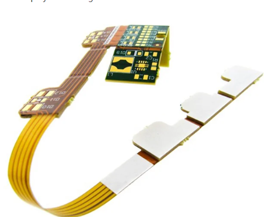
Flexible printed circuit boards (FPCBs) have become essential in modern electronics due to their lightweight, bendable, and space-saving properties. One critical aspect of FPCB assembly is crimping, a process used to establish reliable electrical connections between flexible circuits and connectors or other components. Crimping ensures mechanical stability and electrical conductivity without the need for soldering, making it ideal for high-density and high-reliability applications.
This article explores flexible PCB crimping, covering its techniques, advantages, challenges, and best practices to ensure optimal performance in various electronic applications.
1. What is Flexible PCB Crimping?
Crimping is a mechanical process that joins a flexible PCB to a connector or terminal by deforming a metal crimp barrel around the conductors. Unlike soldering, crimping does not involve heat, reducing the risk of thermal damage to the flexible substrate.
Key Components in Crimping:
- Crimp Connector: A metal terminal designed to grip the FPCB conductors.
- Anvil and Crimper: Tools that apply pressure to deform the crimp barrel.
- Flexible PCB Conductors: Typically made of copper with or without plating (e.g., gold or tin).
Types of Crimping for Flexible PCBs:
- Insulation Displacement Crimping (IDC): Pierces the insulation to make contact with conductors.
- Open-Barrel Crimping: Uses a U-shaped terminal that closes around the conductor.
- Closed-Barrel Crimping: Encases the conductor fully for better strain relief.
2. Advantages of Crimping Flexible PCBs
Crimping offers several benefits over soldering and other connection methods:
A. No Thermal Stress
- Since crimping is a cold process, it avoids heat-related damage to thin flexible substrates.
B. High Reliability
- Proper crimping ensures strong mechanical and electrical bonds, resistant to vibration and shock.
C. Faster Assembly
- Automated crimping machines enable rapid, consistent connections in mass production.
D. Better for Fine-Pitch Applications
- Crimping supports high-density interconnects, making it suitable for miniaturized electronics.
E. Compatibility with Various Materials
- Works with polyimide, PET, and other flexible PCB materials.
3. Challenges in Flexible PCB Crimping
Despite its advantages, crimping FPCBs presents unique challenges:
A. Delicate Substrates
- Flexible PCBs are thinner and more prone to tearing or deformation under excessive pressure.
B. Alignment Issues
- Misalignment during crimping can lead to poor electrical contact or short circuits.
C. Crimp Force Control
- Insufficient force causes weak connections, while excessive force damages conductors.
D. Environmental Factors
- Humidity and temperature fluctuations may affect crimp integrity over time.
4. Crimping Techniques for Flexible PCBs
To achieve high-quality crimps, manufacturers use specialized techniques:
A. Precision Tool Selection
- Use crimping tools with adjustable pressure settings to match the FPCB thickness.
B. Automated Crimping Machines
- Robotic crimping ensures consistency and reduces human error.
C. Strain Relief Design
- Adding reinforcement (e.g., stiffeners) near crimp points prevents flex fatigue.
D. Pre-Crimp Inspection
- Verify conductor alignment and cleanliness before crimping.
E. Post-Crimp Testing
- Perform pull tests, continuity checks, and microsection analysis to validate crimp quality.
5. Applications of Crimped Flexible PCBs
Crimped FPCBs are widely used in industries requiring robust, flexible interconnects:
A. Consumer Electronics
- Smartphones, laptops, and wearables use crimped flex circuits for display and battery connections.
B. Automotive Systems
- Flex circuits in dashboards, sensors, and LED lighting rely on crimping for vibration resistance.
C. Medical Devices
- Implantable and wearable medical electronics use crimped connections for reliability.
D. Aerospace & Defense
- Crimped FPCBs withstand extreme conditions in avionics and military equipment.
E. Industrial Automation
- Robotics and machinery use crimped flex circuits for dynamic movement.
6. Best Practices for Flexible PCB Crimping
To ensure optimal crimp quality, follow these guidelines:
A. Material Selection
- Choose crimp terminals compatible with the FPCB’s conductor material (e.g., gold-plated for high reliability).
B. Proper Tool Calibration
- Regularly calibrate crimping tools to maintain consistent force.
C. Controlled Environment
- Crimp in low-humidity, temperature-controlled settings to prevent oxidation.
D. Use of Adhesives (When Needed)
- Apply conductive adhesives for additional mechanical support in high-stress applications.
E. Compliance with Industry Standards
- Follow IPC/WHMA-A-620 and other relevant standards for crimp quality.
7. Future Trends in Flexible PCB Crimping
Advancements in crimping technology include:
- Laser-Assisted Crimping: Improves precision for ultra-fine-pitch FPCBs.
- Smart Crimping Systems: AI-driven quality control for defect detection.
- Eco-Friendly Crimp Materials: Lead-free and recyclable crimp terminals.
Conclusion
Flexible PCB crimping is a vital process in modern electronics manufacturing, offering a reliable, solder-free alternative for interconnecting flexible circuits. By understanding crimping techniques, challenges, and best practices, engineers can ensure durable and high-performance connections in applications ranging from consumer gadgets to aerospace systems. As technology evolves, innovations in crimping will further enhance the capabilities of flexible electronics.