Basic knowledge that must be understood in high-temperature IC design: ambient temperature and junction temperature
With the rapid development of technology, the demand for high-temperature resistant integrated circuits (ICs) in the fields of commerce, industry, military and automobile continues to rise. High temperature environments will seriously restrict the performance, reliability and safety of integrated circuits, and it is urgent to overcome related technical difficulties through innovative technical means.
This article is dedicated to exploring the impact of high temperature on integrated circuits and providing design techniques for high power to meet these challenges. By deeply analyzing the root causes of high temperature, we aim to alleviate the problems caused by it, thereby enhancing the robustness of integrated circuits under extreme conditions and extending their service life, while optimizing the cost of the overall solution. ON Semiconductor’s Treo platform provides a comprehensive product development ecosystem designed to support high-temperature operation. This article is the first one and will focus on the introduction of operating temperature, including ambient temperature and junction temperature.

Ambient temperature
A key parameter of ICs and all electronic devices is the temperature range in which they can operate reliably. The specific operating temperature range is defined by the application and industry (Figure 1a).
For automotive ICs, for example, the temperature range depends on where the electronics are mounted. If located in the passenger compartment, the temperature range can be up to 85°C. If located in the chassis or engine compartment, but not directly on the engine, the temperature range can be up to 125°C. Close to or directly near the engine or transmission, the temperature range can be up to 150°C or 160°C. In chassis areas near brakes or hydraulic systems, the temperature can reach up to 175°C. These high temperature requirements apply to internal combustion engine vehicles, but also to hybrid and fully electric vehicles.
When the vehicle engine is running, active cooling systems effectively control the temperature. However, in the most extreme cases, such as when the vehicle is parked in a hot environment after driving, the active cooling system stops working and the heat from the engine and other components gradually dissipates, causing the electronics to heat up. Even so, when the car is started again, all systems must continue to operate normally under the elevated temperature conditions.
For moderate temperature conditions, the expected service life of the IC at static operating temperature can be defined. For example, 10 years of continuous operation at 125°C is possible. However, high temperatures such as 175°C are not practically achievable using bulk CMOS processes. Typically, ICs do not need to operate at maximum temperatures throughout their lifetime. In the automotive industry, thermal profiles are often used instead of fixed static temperature specifications, dividing the entire lifetime into different operating modes and temperature ranges (segments), with only a small portion of the time requiring operation at very high temperatures (Figure 1b).
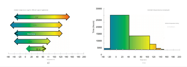
Figure 1. Example of temperature ranges and temperature profiles for different applications
Placing electronic components closer to the application’s high-temperature area can improve sensor accuracy and resolution by reducing noise and interference. For high-power applications, minimizing high-current switching loops can reduce interference. Using local closed-loop control systems can reduce weight and improve performance. However, reducing module size will increase the temperature of electronic components due to increased power density and heat dissipation issues.
Junction temperature
ICs consume power when operating, causing the actual semiconductor junction temperature inside the IC to be higher than the ambient temperature. The temperature rise depends on the power dissipated inside the IC and the thermal resistance between the die and the environment. This thermal resistance depends on the package type, PCB, heat sink, etc. (see Figure 2).
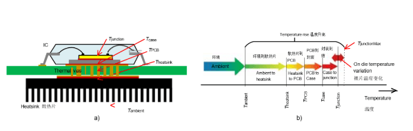
Figure 2. Junction temperature rise
For power switches, power drivers, DC-DC converters, linear regulators with high voltage dropout (e.g. for automotive battery drive modules when using a DC-DC converter is not economical) or sensor actuators, high die power dissipation is inevitable.
Thermal resistance depends on the package type and thermal management (Figure 3). For commonly used small packages, the thermal resistance from junction to ambient is about 50-90K/W (SOIC package) and about 30-60K/W (QFP package). In some applications, the thermal resistance from junction to ambient can reach hundreds of Kelvin per Watt.
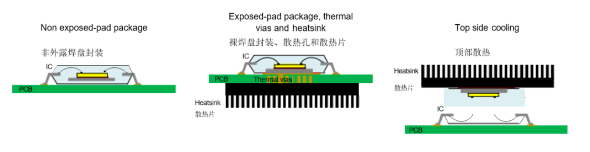
Figure 3. Example of IC heat dissipation in different package types
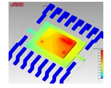
The junction temperature is not uniform over the entire die of the IC. There may be areas of high power dissipation, such as power drivers. An example of an IC die temperature graph with a high power driver is shown in Figure 4.