Thermal Management Methods for High-Power PCBs
Introduction
As electronic devices continue to push performance boundaries with higher power densities and more compact designs, effective thermal management has become one of the most critical challenges in printed circuit board (PCB) design. High-power PCBs, commonly found in power electronics, automotive systems, industrial equipment, and high-performance computing, generate substantial amounts of heat that must be properly dissipated to ensure reliability, longevity, and optimal performance.
This article examines various thermal management techniques for high-power PCBs, covering material selection, design strategies, and advanced cooling solutions. Proper implementation of these methods can prevent thermal runaway, reduce mechanical stress, minimize performance degradation, and significantly extend the operational life of electronic components.
1. PCB Material Selection for Thermal Management
1.1 High Thermal Conductivity Substrates
Traditional FR-4 material, while cost-effective, has relatively poor thermal conductivity (about 0.3 W/mK). For high-power applications, alternative substrate materials offer better thermal performance:
- Metal Core PCBs (MCPCBs): These incorporate a metal base (typically aluminum or copper) with thermal conductivity ranging from 120-400 W/mK. The metal layer acts as a heat spreader, efficiently transferring heat away from components.
- Ceramic Substrates: Materials like aluminum oxide (Al₂O₃, 24-28 W/mK) and aluminum nitride (AlN, 140-180 W/mK) provide excellent thermal performance and electrical insulation. These are particularly valuable in high-frequency, high-power applications.
- Thermally Enhanced Organic Laminates: Materials like Rogers’ thermally conductive laminates or Isola’s TerraGreen offer improved thermal conductivity (up to 1.5 W/mK) while maintaining familiar PCB manufacturing processes.
1.2 Thermal Interface Materials (TIMs)
TIMs play a crucial role in minimizing thermal resistance between components and heat sinks:
- Thermal Pads: Easy-to-apply, non-conductive materials with thermal conductivity up to 12 W/mK
- Thermal Greases/Pastes: Offer lower thermal resistance but can be messy to apply (3-8 W/mK)
- Phase Change Materials: Combine ease of application with performance approaching thermal greases
- Thermal Adhesives: Provide both mechanical bonding and thermal conduction (1-4 W/mK)
- Gap Fillers: Compressible materials that accommodate uneven surfaces while conducting heat
2. PCB Layout and Design Strategies
2.1 Copper Utilization and Thermal Relief
- Copper Thickness: Increasing copper weight (2 oz to 4 oz or more) improves current carrying capacity and heat spreading
- Thermal Planes: Dedicated copper layers connected to heat-generating components act as internal heat spreaders
- Thermal Vias: Arrays of vias under hot components conduct heat to other layers. Filled and plugged vias offer better performance
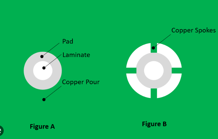
- Copper Pour: Flooding unused board areas with copper connected to ground helps distribute heat
2.2 Component Placement and Orientation
- Strategic Spacing: Allow adequate space between high-power components to prevent thermal interference
- Airflow Consideration: Orient components to take advantage of natural or forced convection currents
- Thermal Zoning: Group components by thermal characteristics to optimize cooling strategies
- Board Edge Placement: Position very high-power devices near board edges for easier heat sink attachment
2.3 Trace Design Considerations
- Wide Traces: Reduce resistance and associated I²R heating
- Teardrop Transitions: Minimize heating at trace width changes
- Current Density Analysis: Ensure traces can handle expected current without excessive heating
- Surface vs. Internal Routing: Balance thermal and electrical requirements
3. Active and Passive Cooling Solutions
3.1 Heat Sinks
- Stamped Metal: Economical solution for moderate power applications
- Extruded Aluminum: Offers excellent performance-to-cost ratio
- Bonded Fin: Provides high surface area in compact spaces
- Skived: Thin, closely spaced fins for high-performance applications
- Integrated Heat Spreaders: Built into component packages or PCB substrates
3.2 Forced Air Cooling
- Axial Fans: Common for general-purpose cooling
- Blower Fans: Provide directed airflow in confined spaces
- Piezoelectric Fans: Low-power, low-noise alternative for small systems
- Airflow Optimization: Use baffles, ducts, and vents to direct cooling where needed
3.3 Liquid Cooling
- Cold Plates: Metal blocks with internal channels mounted to PCBs
- Microchannel Coolers: High-efficiency cooling for very high power densities
- Immersion Cooling: Submerging entire PCBs in dielectric fluids
- Heat Pipes: Passive two-phase cooling devices effective for localized hot spots
3.4 Advanced Cooling Technologies
- Vapor Chambers: Two-dimensional heat spreaders for uniform temperature distribution
- Thermoelectric Coolers: Solid-state devices for precise temperature control
- Phase Change Materials: Absorb heat during melting for transient thermal management
- Nanostructured Surfaces: Enhanced heat transfer surfaces under development
4. Thermal Analysis and Simulation
Effective thermal management begins with accurate thermal modeling:
- Finite Element Analysis (FEA): Detailed 3D modeling of heat flow
- Computational Fluid Dynamics (CFD): Simulates airflow and convective cooling
- Lumped Parameter Modeling: Faster analysis for system-level thermal performance
- Infrared Thermography: Validates thermal performance of physical prototypes
- Thermal Resistance Networks: Calculates θJA (junction-to-ambient) and other critical metrics
5. System-Level Thermal Considerations
- Enclosure Design: Affects airflow and convective cooling
- Altitude and Environment: Impacts cooling efficiency (reduced at higher altitudes)
- Orientation: Natural convection performance varies with board angle
- Operational Profile: Duty cycles affect thermal design requirements
- Redundancy: Critical systems may need backup cooling systems
Conclusion
Thermal management for high-power PCBs requires a holistic approach combining material science, mechanical engineering, and electrical design expertise. As power densities continue to increase with advancing semiconductor technologies, thermal management will remain a key differentiator in electronic product design. Future developments in materials (such as graphene-enhanced substrates), advanced manufacturing techniques (like embedded cooling channels), and smart thermal management systems (with real-time adaptive control) promise to push the boundaries of what’s possible in high-power electronics cooling.
Designers must carefully evaluate their specific requirements—including power levels, size constraints, environmental conditions, and cost targets—to select the most appropriate combination of thermal management techniques. Proper implementation not only ensures reliable operation but can also lead to significant improvements in energy efficiency, product lifetime, and overall system performance.

