Why PCB Impedance Can Be Controlled: A Comprehensive Analysis
Introduction
Printed Circuit Board (PCB) impedance control has become increasingly critical in modern electronics design, particularly with the rise of high-speed digital circuits and high-frequency analog applications. The ability to precisely control impedance in PCB traces ensures signal integrity, minimizes reflections, and reduces electromagnetic interference (EMI). This article explores the fundamental reasons why PCB impedance can be controlled, examining the underlying physics, material properties, design parameters, and manufacturing techniques that make this control possible.
1. Understanding Transmission Line Theory
The foundation of impedance control lies in transmission line theory. When signal frequencies exceed certain thresholds (typically when trace lengths approach 1/10 of the signal wavelength), PCB traces behave not as simple conductors but as transmission lines. This transition occurs because:
- The distributed capacitance between the trace and reference plane becomes significant
- The distributed inductance along the trace length affects signal propagation
- The time delay along the trace becomes comparable to signal rise times
For controlled impedance applications, traces are designed to maintain a consistent characteristic impedance (Z₀) along their entire length, given by:
Z₀ = √(L/C)
Where L is the distributed inductance per unit length and C is the distributed capacitance per unit length. This equation reveals that impedance depends on physical dimensions and material properties that can be precisely controlled during design and manufacturing.
2. Key Parameters Affecting PCB Impedance
Several controllable parameters determine the characteristic impedance of PCB traces:
2.1 Trace Geometry
- Trace width (W): Wider traces lower impedance by increasing capacitance and reducing inductance
- Trace thickness (T): Thicker traces similarly lower impedance
- Trace cross-sectional shape: Affects current distribution and thus inductance
2.2 Dielectric Properties
- Dielectric thickness (H): Thicker dielectrics increase impedance by reducing capacitance
- Dielectric constant (Dk or εᵣ): Materials with lower Dk yield higher impedance
- Dielectric consistency: Uniformity prevents impedance variations along the trace
2.3 Reference Plane Configuration
- Distance to reference plane: Closer planes increase capacitance, lowering impedance
- Reference plane continuity: Gaps or splits cause impedance discontinuities
- Multiple reference layers: Affects electromagnetic field distribution
2.4 Surrounding Environment
- Solder mask: Affects the effective dielectric constant near the trace
- Adjacent traces: Coupling alters effective capacitance and inductance
- Board finish: Surface roughness affects high-frequency resistance
3. Material Control for Impedance Management
Modern PCB materials enable precise impedance control through:
3.1 Consistent Dielectric Materials
- Manufacturer-controlled Dk tolerance (typically ±0.5 to ±0.05)
- Low dispersion materials maintain consistent Dk across frequencies
- Uniform thickness achieved through precise manufacturing processes
3.2 Copper Foil Characteristics
- Electrodeposited vs. rolled copper affects surface roughness
- Thickness control (typically ±10% or better)
- Surface treatment for consistent adhesion and roughness
3.3 Prepreg and Core Materials
- Glass weave style affects local Dk variations
- Resin content controls overall dielectric properties
- Curing processes ensure material consistency
4. Design Techniques for Impedance Control
PCB designers employ multiple strategies to achieve target impedances:
4.1 Stackup Design
- Calculated dielectric thicknesses between layers
- Symmetrical constructions to prevent warpage and maintain consistency
- Controlled differential pair spacing for coupled lines
4.2 Trace Routing Practices
- Avoiding abrupt changes in width or direction
- Maintaining consistent spacing to reference planes
- Length matching for differential pairs
4.3 Simulation and Modeling
- 2D field solvers calculate impedance from cross-sections
- 3D electromagnetic simulation for complex structures
- Manufacturing tolerance analysis to ensure yield
5. Manufacturing Processes Enabling Impedance Control
Modern PCB fabrication has developed specialized processes for impedance control:
5.1 Etching Precision
- Laser direct imaging (LDI) for precise trace definition
- Compensated artwork accounts for etching factors
- Automated optical inspection (AOI) verifies trace dimensions
5.2 Lamination Control
- Precision dielectric thickness through controlled prepreg flow
- Pressure and temperature profiling for consistent material properties
- Impedance test coupons for process verification
5.3 Testing and Verification
- Time domain reflectometry (TDR) for impedance measurement
- Cross-section analysis for dimensional verification
- Statistical process control to maintain tolerances
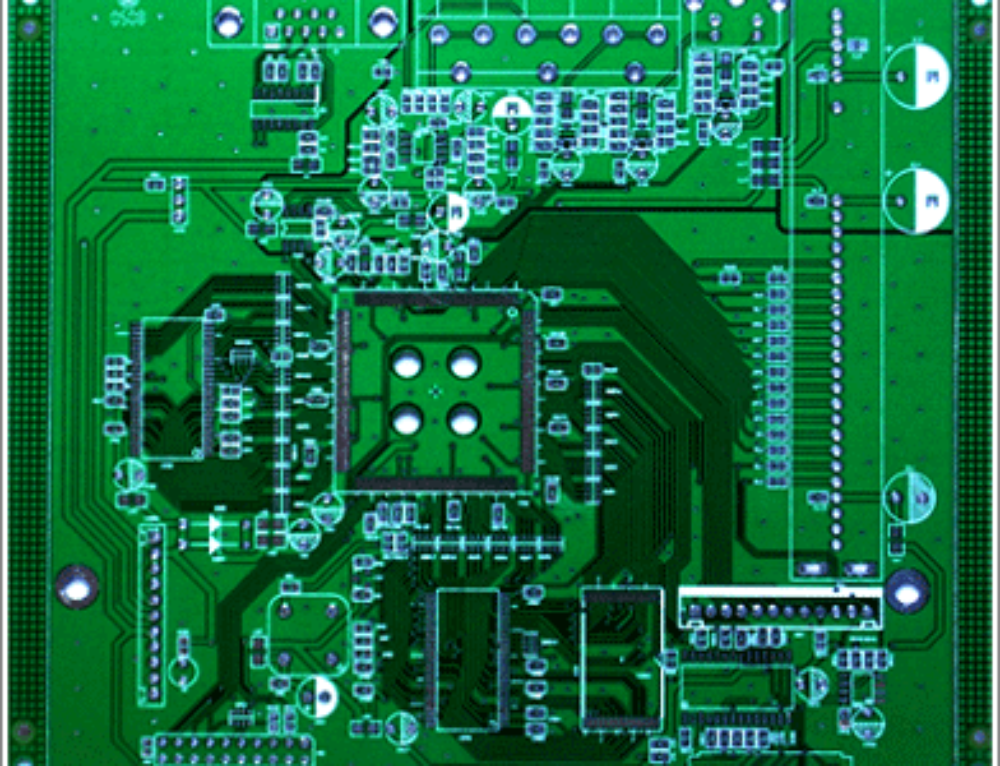
6. Common Controlled Impedance Structures
Different PCB configurations offer specific impedance control approaches:
6.1 Microstrip
- Single trace over reference plane
- Exposed to air on one side
- Common for outer layers
- Impedance affected by solder mask
6.2 Stripline
- Trace embedded between two reference planes
- Symmetrical or asymmetrical configurations
- More stable impedance but harder to fabricate
6.3 Coplanar Waveguide
- Trace with adjacent grounded copper
- Reduced dependence on dielectric thickness
- Useful for high-frequency designs
7. Tolerance Analysis and Yield Management
Achieving consistent impedance requires understanding and controlling variations:
- Material property tolerances (Dk, thickness)
- Manufacturing process variations (etching, lamination)
- Environmental factors (temperature, humidity)
- Design margin to accommodate variations
Typical impedance control tolerances range from ±10% for standard designs to ±5% or better for high-performance applications.
8. Advanced Techniques for Tight Impedance Control
Emerging technologies enable even better impedance management:
- Laser ablation for ultra-precise trace formation
- Modified resin systems with tighter Dk control
- Nanostructured materials for consistent properties
- In-line impedance testing for real-time adjustment
9. Practical Considerations in Impedance Control
Successful implementation requires attention to:
- Cost vs. performance tradeoffs
- Manufacturer capabilities and experience
- Design for manufacturability (DFM) principles
- Testing and validation strategies
Conclusion
PCB impedance can be precisely controlled through a combination of fundamental electromagnetic principles, carefully selected materials, sophisticated design techniques, and advanced manufacturing processes. The ability to manage impedance stems from controlling the geometric and material parameters that determine the distributed capacitance and inductance of PCB traces. As electronic systems continue to operate at higher frequencies and faster edge rates, impedance control becomes not just possible but essential for reliable circuit operation. Ongoing advancements in materials science, fabrication technologies, and design tools continue to improve the precision and reliability of impedance-controlled PCBs, enabling the next generation of high-performance electronic systems.