Reasons for Opening Windows in PCB Solder Mask Layers
Abstract
The solder mask layer is a critical component in printed circuit board (PCB) manufacturing, providing insulation, protection against oxidation, and preventing solder bridges. However, designers often create openings (windows) in the solder mask for specific purposes. This article explores the key reasons for opening solder mask windows, including electrical connectivity, thermal management, component soldering, testing, and mechanical considerations. Understanding these reasons helps optimize PCB design for performance, reliability, and manufacturability.
1. Introduction
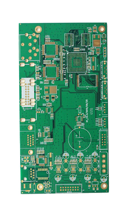
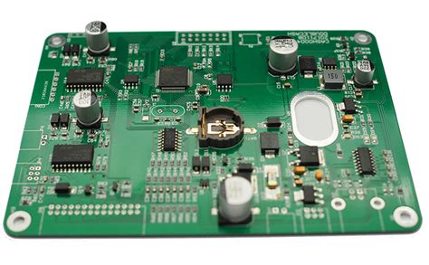
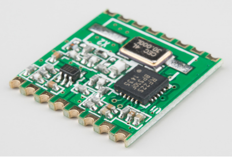
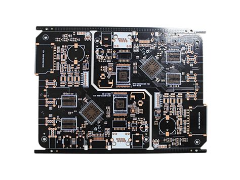
The solder mask, typically a green epoxy layer, covers copper traces on a PCB to prevent short circuits, corrosion, and solder bridging. However, certain areas require exposure for functional or assembly reasons. These exposed regions, called “solder mask openings” or “windows,” serve multiple purposes in PCB design. This article examines the primary reasons for solder mask openings and their implications.
2. Reasons for Solder Mask Openings
2.1. Electrical Connectivity
One of the most common reasons for solder mask openings is to establish electrical connections:
- Component Pads: SMD (Surface Mount Device) pads must remain exposed to allow solder paste application and component attachment.
- Through-Hole Components: Plated through-holes (PTH) require solder mask openings to facilitate soldering of leads.
- Test Points: Test points used for debugging or validation must be exposed for probe contact.
- High-Current Traces: Large power traces may have openings to allow additional solder or copper thickening for higher current capacity.
2.2. Thermal Management
Solder mask acts as an insulator, which can hinder heat dissipation. Openings are used to enhance thermal performance:
- Heat Sink Attachment: Exposed copper areas allow direct bonding of heat sinks for better thermal transfer.
- High-Power Components: Power devices (e.g., MOSFETs, regulators) may have exposed pads to dissipate heat efficiently.
- Thermal Relief Pads: Some designs use solder mask openings to balance heat distribution during soldering.
2.3. Soldering and Assembly Requirements
Certain assembly processes necessitate solder mask openings:
- Hand Soldering Areas: Technicians may need access to specific pads for rework or manual soldering.
- Selective Soldering: Some PCBs use solder mask-defined pads to control solder flow in mixed-technology boards.
- Press-Fit Connectors: These components require precise openings for mechanical insertion without solder interference.
2.4. Testing and Probing
PCBs undergo electrical testing, and solder mask openings facilitate access:
- Flying Probe Testing: Exposed test pads allow probes to make contact without damaging the solder mask.
- Boundary Scan (JTAG): Test points for JTAG debugging must be accessible.
- In-Circuit Testing (ICT): Dedicated test points require openings for reliable electrical contact.
2.5. Mechanical and Structural Considerations
Some PCB designs incorporate solder mask openings for mechanical reasons:
- EMI Shielding: Metal shielding cans may need direct contact with exposed grounding pads.
- Connector Alignment: Openings ensure precise placement of connectors and mechanical components.
- Flexible PCBs: Solder mask openings in flex areas reduce stress and improve bendability.
2.6. Specialized Applications
Certain advanced PCB applications require unique solder mask configurations:
- High-Frequency RF Designs: Controlled impedance traces may need precise solder mask openings to minimize dielectric effects.
- LED PCBs: Exposed copper improves reflectivity and heat dissipation in LED arrays.
- Battery Contacts: Direct metal exposure ensures reliable electrical connections in battery-powered devices.
3. Design Considerations for Solder Mask Openings
While solder mask openings are beneficial, improper design can lead to issues:
- Solder Bridging: Excessive openings may increase the risk of unintended solder connections.
- Corrosion Risk: Exposed copper can oxidize if not properly treated (e.g., ENIG, HASL).
- Manufacturing Tolerances: Designers must account for solder mask expansion/contraction during fabrication.
4. Conclusion
Solder mask openings are essential for electrical, thermal, mechanical, and assembly requirements in PCB design. By understanding the reasons behind these openings—such as component soldering, testing, heat dissipation, and specialized applications—designers can optimize their PCBs for performance and reliability. Proper implementation ensures manufacturability while avoiding potential pitfalls like solder bridging or corrosion.
5. References
- IPC-7351, “Generic Requirements for Surface Mount Design and Land Pattern Standard”
- IPC-SM-840, “Qualification and Performance Specification of Permanent Solder Mask”
- “PCB Design for Real-World EMI Control” by Bruce R. Archambeault
This article provides a comprehensive overview of why solder mask openings are used in PCB design, helping engineers make informed decisions for their projects.

