Defining PCB Process Edges: A Comprehensive Guide
Introduction
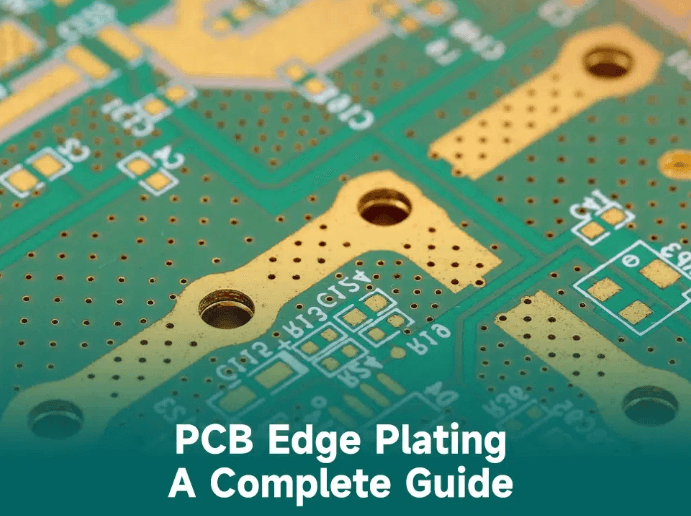
Printed Circuit Boards (PCBs) are essential components in modern electronics, providing mechanical support and electrical connections for electronic components. One critical aspect of PCB design and manufacturing is the definition and utilization of process edges (also known as routing tabs, breakaway tabs, or panel borders). Process edges are the extra margins added around the PCB panel to facilitate handling during fabrication, assembly, and testing.
This article explores the definition of PCB process edges, their importance, design considerations, and industry best practices to ensure efficient manufacturing and assembly.
1. What Are PCB Process Edges?
Process edges refer to the additional border areas added around individual PCBs or PCB arrays within a manufacturing panel. These edges serve multiple purposes:
- Mechanical Support: They provide stability during handling, preventing warping or damage.
- Automated Assembly: Machines (such as pick-and-place systems) require gripping areas for precise component placement.
- Testing & Inspection: Process edges allow fixtures to hold the PCB during electrical testing.
- Depanelization: They facilitate the separation of individual PCBs from the panel after assembly.
Process edges are typically removed (via routing, scoring, or breaking) after assembly, leaving the final PCB in its intended form.
2. Why Are Process Edges Necessary?
2.1 Manufacturing and Handling
- PCB fabrication involves multiple processes (etching, drilling, plating, soldering), and process edges ensure the panel remains rigid.
- Automated machinery (such as conveyors and optical inspection systems) requires gripping areas to move PCBs smoothly.
2.2 SMT Assembly
- Surface Mount Technology (SMT) machines need reference points (fiducial marks) on process edges for accurate component placement.
- The edges prevent misalignment when boards pass through reflow ovens.
2.3 Depanelization
- After assembly, PCBs must be separated from the panel. Process edges allow for clean breakaway via V-scoring, tab routing, or laser cutting.
2.4 Testing & Fixturing
- In-circuit testing (ICT) and functional testing require fixtures that clamp onto the process edges to ensure electrical contact.
3. Key Design Considerations for PCB Process Edges
When defining process edges, engineers must consider several factors to optimize manufacturability and assembly efficiency.
3.1 Width of Process Edges
- Standard Width: Typically 5mm to 10mm per side, but may vary based on panel size and assembly requirements.
- Minimum Width: Should be at least 3mm to ensure machine gripping without slippage.
- Large PCBs: May require wider edges (up to 15mm) for added rigidity.
3.2 Fiducial Marks and Tooling Holes
- Fiducial Marks: Optical alignment markers placed on process edges to guide automated assembly machines.
- Tooling Holes: Used for panel alignment during drilling and assembly (usually 3mm diameter).
3.3 Depanelization Methods
The choice of depanelization affects process edge design:
- V-Scoring: A V-shaped groove allows easy breaking but requires a straight edge.
- Tab Routing: Small tabs hold PCBs in place; they are later broken or cut.
- Laser Cutting: Precise but more expensive; requires minimal edge clearance.
3.4 Copper and Solder Mask Clearance
- Avoid placing copper traces or components too close to the edge to prevent peeling during depaneling.
- A 0.5mm to 1mm clearance from the board edge is recommended.
3.5 Panel Utilization Efficiency
- Process edges reduce the usable panel area, so designers must balance edge width with material cost efficiency.
- Nesting multiple PCBs in a panel can optimize space usage.
4. Common PCB Process Edge Configurations
4.1 Single PCB with Process Edges
- A standalone PCB with borders on all sides (common for larger boards).
4.2 Multi-PCB Panel with Breakaway Tabs
- Multiple PCBs arranged in an array with process edges around the perimeter and breakaway tabs between individual boards.
4.3 Mouse Bites (Micro-Tabs)
- Small perforated tabs (0.3mm to 0.5mm) hold PCBs in place, allowing easy manual separation.
4.4 Rails for Conveyor Handling
- Some designs include extended rails (wider edges) for conveyor-based assembly lines.
5. Best Practices for Defining PCB Process Edges
- Consult Manufacturer Guidelines: Different PCB fabricators may have specific requirements for edge width and tooling holes.
- Minimize Waste: Optimize panel layout to reduce material costs while ensuring manufacturability.
- Ensure Depanelization Compatibility: Choose a method (V-scoring, routing, laser) that suits the PCB’s design and assembly process.
- Avoid Critical Components Near Edges: Keep sensitive traces and components at least 2mm away from the edge to prevent damage.
- Use Standardized Fiducial Marks: Follow IPC-7351 standards for fiducial placement to ensure machine compatibility.
6. Conclusion
PCB process edges play a crucial role in ensuring efficient manufacturing, assembly, and testing of circuit boards. Properly defining these edges involves balancing mechanical stability, assembly requirements, and cost efficiency. By following industry best practices and collaborating with fabrication partners, designers can optimize PCB layouts for high-quality production.
Understanding the importance of process edges helps prevent manufacturing defects, reduces assembly errors, and ensures reliable end products. Whether designing simple single-layer PCBs or complex multi-layer boards, careful consideration of process edges is essential for successful PCB fabrication and assembly.