Detection Circuit in PCB Reverse Design System
1 Introduction
When electronic engineers are performing reverse design or repair work on electronic equipment, they first need to understand the connection relationship between the components on the unknown printed circuit board (PCB), so they need to measure and record the connectivity relationship between the pins of each component on the PCB.
The simplest method is to set the multimeter to the “short circuit buzzer” position, use two test pens to measure the connectivity relationship between the pins one by one, and then manually record the on/off circuit status between the “pin pairs”. In order to obtain the full set of connection relationships between all “pin pairs”, the “pin pairs” to be measured must be organized according to the combination principle. When the number of components and pins on the PCB is large, the number of “pin pairs” that need to be measured will be very large. Obviously, if manual methods are used to do this work, the workload of measurement, recording and calibration will be very large. Moreover, the measurement accuracy is low. As we all know, when the resistive impedance value between the two test pens of a general multimeter is as high as about 20 ohms, its buzzer will still make a sound, indicating a connection.
In order to improve the measurement efficiency, it is necessary to find a way to realize the automatic measurement, recording and calibration of the component “pin pairs”. For this purpose, the author designed a path detector controlled by a microcontroller as a front-end detection device, and designed a set of powerful measurement navigation software for back-end processing, which together realize the automatic measurement and recording of the path relationship between component pins on the PCB. This article mainly discusses the design ideas and technologies of the path detection circuit to realize automatic measurement.
The premise of realizing automatic measurement is to connect the pins of the measured component into the detection circuit. For this purpose, the detection equipment is equipped with several measuring heads, which are led out through cables. The measuring heads can be connected to various test fixtures and component pins to establish connections. The number of measuring heads determines the number of pins connected to the detection circuit in the same batch. Then, under program control, the detector sequentially includes the measured “pin pairs” into the measurement path one by one according to the combination principle. In the measurement path, the on/off state between the “pin pairs” is presented as whether there is resistance between the pins. The measurement path converts it into a voltage quantity, thereby judging the on/off relationship between them and recording it.
The PCB path detection circuit based on this idea should mainly realize three functions:
Automatically select the “pin pair” to be tested and measure it;
Automatically determine the path relationship between the “pin pairs”;
Automatically record the measurement results.
2 Automatic selection and measurement of the pin pair to be tested.
2.1 Automatic switching of the pin pair to be tested
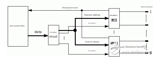
In order to enable the detection circuit to select different pins for measurement in turn from the many measuring heads connected to the component pins according to the combination principle, the corresponding switch array can be set, and the program opens/closes different switches to switch the component pins into the measurement path to obtain their on/off relationship. Since the measured value is an analog voltage quantity, an analog multi-way switch should be used to form a switch array. Figure 1 shows the idea of using an analog switch array to realize the switching of the measured pins.
2.2 Measurement of on/off relationship
The design principle of the detection circuit is shown in Figure 2. The two groups of analog switches in the two boxes Ⅰ and Ⅱ in the figure are configured in pairs: Ⅰ-1 and Ⅱ-1, Ⅰ-2 and Ⅱ-2, . . . . . , Ⅰ-N and Ⅱ-N. The closing or closing of the analog multi-way switch is controlled by the program through the decoding circuit shown in Figure 1. At most, only one switch can be closed at the same time in the two analog switches Ⅰ and Ⅱ. For example, to detect whether there is a path relationship between measuring head 1 and measuring head 2, the Ⅰ-1 and Ⅱ-2 switches are closed, and a measurement path is formed between point A and the ground through measuring heads 1 and 2. If there is a path, the voltage VA at point A = 0; if there is an open circuit, VA> 0. The value of VA is the basis for judging whether there is a path relationship between measuring heads 1 and 2. In this way, the on/off relationship between all pins connected to the measuring head can be measured instantly according to the combination principle. Since this measurement process is carried out between the pins of the components clamped by the test fixture, the author calls it in-clamp measurement.
If the pins of the component cannot be clamped, the measurement must be performed with a test lead. As shown in Figure 2, connect one probe to an analog channel and the other to ground. At this time, as long as the switch Ⅰ-1 is closed, the measurement can be carried out, which is called pen-by-pen measurement. The circuit shown in Figure 2 can also instantly complete the measurement between all the clampable pins of the hanging measuring head and the non-clampable pins touched by the grounded probe. At this time, the closure of each switch of Ⅰ channel needs to be controlled in turn, while each switch of Ⅱ channel is always open. This measurement process can be called pen-clip measurement.
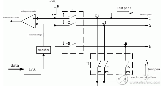
Figure 2 Principle of detection circuit
3 Judgment of path relationship
3.1 Proposal of threshold voltage
As can be seen from Figure 2, if VA is used as the measured voltage, theoretically when VA=0, it should be a path, and when VA>0, it should be an open circuit, and the value of VA varies with the resistance value between the two measurement channels. However, since the analog multi-way switch itself has a non-negligible on-resistance RON, after the measurement path is formed, if it is a path, VA is not equal to 0, but equal to the voltage drop on RON. Since the purpose of the measurement is only to know the on/off relationship, there is no need to measure the specific value of VA. For this purpose, it is only necessary to use a voltage comparator to compare whether VA is greater than the voltage drop on RON. Set the threshold voltage of the voltage comparator equal to the voltage drop on RON, and the output of the voltage comparator is the measurement result, which is a digital quantity that can be directly read by the microcontroller.
3.2 Determination of threshold voltage value
Experiments have found that RON has individual differences and is also related to the ambient temperature, so the loaded threshold voltage needs to be set one by one with the closed analog switch channel, which can be achieved by programming the D/A converter.
The circuit shown in Figure 2 can be used to easily determine the threshold data. The method is to close the switch pairs Ⅰ-1, Ⅱ-1; Ⅰ-2, Ⅱ-2; …; Ⅰ-N, Ⅱ-N in sequence to form a path loop. After each pair of switches is closed, send a number to the D/A converter, and the number sent increases from small to large, and measure the output of the voltage comparator at this time. When the output of the voltage comparator changes from 1 to 0, the data at this time corresponds to VA. In this way, the VA of each channel when it is connected can be measured, that is, the voltage drop on RON when a pair of switches are closed. For high-precision analog multi-way switches, the individual differences in their RON are small, so half of the VA automatically measured by the system can be approximated as the corresponding data for the voltage drop on each RON of this pair of switches, that is, the threshold data of each analog switch at the current temperature.
3.3 Dynamic setting of threshold voltage
Use the threshold data measured above to build a table. When performing in-clip measurement, take out the corresponding data from the table according to the numbers of the two closed switches, and send their sum to the D/A converter to form the threshold voltage. For pen-clip measurement and pen-pen measurement, since the measurement path only passes through the analog switch of path I, only the threshold data of one switch needs to be loaded.
In addition, since the circuit itself (D/A converter, voltage comparator, etc.) has errors, and there is contact resistance between the test fixture and the pin to be measured during actual measurement, the threshold voltage actually loaded should be based on the threshold determined by the above method and a correction amount should be added to avoid misjudging the path as a break. However, the increased threshold voltage will drown out the small resistance, that is, the small resistance between the two pins will be judged as a path. Therefore, the threshold voltage correction value should be reasonably selected according to the actual situation. Through experiments, this detection circuit can accurately judge the resistance between the two pins with a resistance value greater than 5 ohms, and its accuracy is significantly higher than that of the multimeter.
4 Several special cases of measurement results
4.1Influence of capacitance
When a capacitor is connected between the measured pins, it should be an open circuit relationship, but the measurement path charges the capacitor at the moment the switch is closed, and the two measurement points are like a path. At this time, the measurement result read from the voltage comparator is a path. For this false path phenomenon caused by capacitance, the following two methods can be used to solve it: appropriately increase the measurement current to shorten the charging time, so that the charging process ends before reading the measurement result; add a program segment to check true and false paths in the measurement software (see Part 5).
4.2 Influence of inductance
If there is an inductor between the measured pins, it should be an open circuit relationship, but because the static resistance impedance of the inductor is very small, the result measured by the multimeter is always a path. Contrary to the case of capacitance measurement, at the moment when the analog switch is closed, due to the induced electromotive force of the inductor, the inductor can be correctly judged by using the fast acquisition speed of the detection circuit. However, this is inconsistent with the measurement requirements of capacitance.
4.3 The influence of analog switch jitter
In actual measurement, it is found that the analog switch has a stable process from the open state to the closed state, which is manifested as the fluctuation of the voltage VA, making the first few measurement results inconsistent. Therefore, it is necessary to judge the results of the path several times and confirm them after the measurement results are consistent.
4.4 Confirmation and recording of measurement results
Considering the above situations, in order to adapt to different measured objects, the software program flowchart shown in Figure 3 is used to confirm and record the measurement results.